

Quasi-continuous-wave (QCW) diode arrays are a critical building block for many high-peak-power solid-state laser systems used in industrial, defense, and scientific applications. Cutting Edge Optronics (CEO) and other leading manufacturers offer QCW arrays with sophisticated packaging, cooling, and reliability features, but the overall performance of the laser system also depends on how these arrays are driven. Selecting and specifying the right laser diode driver is therefore critical for the performance of the system. This blog post provides a practical, engineering-focused guide to specifying a driver for QCW arrays, with emphasis on key electrical, thermal, and control parameters that directly impact performance, reliability, and cost.
This discussion uses information consistent with QCW arrays and drivers manufactured by Cutting Edge Optronics (CEO) and also draws on broader industry practices and reference material from driver manufacturers and technical literature. The goal is to give CTOs, system architects, and laser design engineers a concise yet actionable checklist for driver requirements.
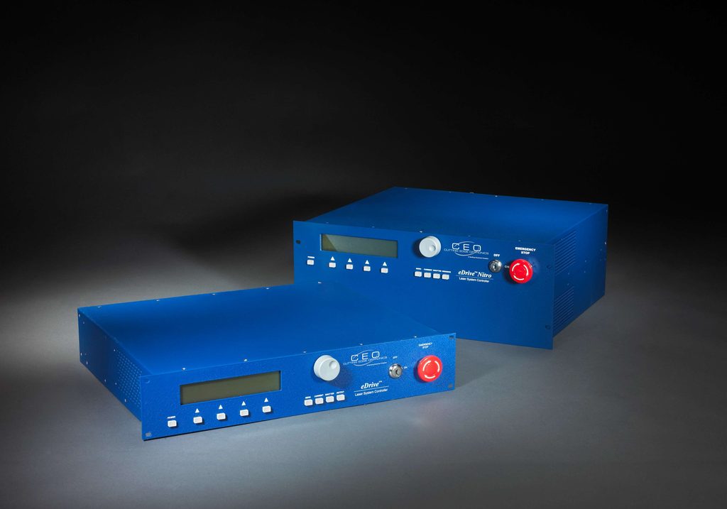
Understanding QCW Diode Arrays and Their Operating Regime
QCW diode arrays bridge the gap between continuous-wave (CW) and strictly pulsed operation. They typically operate with pulse widths from a few microseconds to several milliseconds at duty cycles ranging from a fraction of a percent to several percent. This regime enables very high peak optical power and efficient pumping of solid-state gain media, while keeping average thermal load manageable.
From a driver perspective, QCW operation imposes unique requirements:
• High peak current: QCW diode arrays are often specified for peak drive currents from tens to hundreds of amperes per bar,
• Fast rise and fall times: To achieve well-defined optical pulses and minimize overshoot, the driver must transition quickly while maintaining stable current regulation.
• Tight pulse width and timing control: Pumping efficiency and laser pulse characteristics depend strongly on the electrical pulse shape, so the driver must offer precise timing, jitter control, and synchronization capabilities.
Understanding the basic QCW operating envelope for your specific array—pulse width, repetition rate, duty cycle, peak current, and voltage—is the foundation for specifying a suitable driver.
Key Electrical Specifications for QCW Drivers
The core of any driver specification is its electrical capability. When working with QCW arrays, the following parameters are essential:
1. Current Range and Compliance Voltage
The driver must deliver the required peak current with adequate voltage headroom. For a given array, the forward voltage depends on the number of series elements, temperature, and wavelength band. Cutting Edge Optronics and similar suppliers typically specify forward voltage at a nominal operating current and temperature; use this as the basis for defining the driver’s compliance voltage. Include margin for temperature-induced shifts and wiring losses but avoid excessive overhead, which can increase stress in fault conditions.
2. Current Regulation and Accuracy
High-quality QCW drivers should offer constant-current operation with well-defined tolerance, often less than 2% over the specified range. Poor current regulation leads directly to variability in optical output, reduced pump efficiency, and increased risk of over-driving the diodes. Specify both static accuracy (for a given setpoint) and dynamic behavior (during rise/fall and pulse-to-pulse stability).
3. Pulse Width, Repetition Rate, and Duty Cycle
Define the full range of pulse widths and repetition rates required by your application. For example, you might specify 200 µs to 5 ms pulses at 10–500 Hz, with a maximum duty cycle of 5%. The driver must support these ranges without degradation in current regulation or timing accuracy. It is good practice to explicitly state the minimum and maximum pulse widths and the maximum average current so the supplier can verify that internal components, cooling, and protection circuits are adequate.
4. Rise/Fall Time and Pulse Shape
For many solid-state laser systems, the electrical pulse shape strongly influences optical pulse characteristics. Specify target rise and fall times (e.g., <10 µs) and whether you require square pulses, tailored ramps, or shaped pulses. Some advanced drivers allow user-configurable pulse shaping or feed-forward compensation. If you rely on these features, document them clearly for the supplier.
5. Control Interface and Synchronization
Consider how you will control and synchronize the driver: analog input, digital interface (Ethernet, USB, RS-485), or TTL/CMOS triggers. For multi-channel systems, synchronization between drivers and timing relative to Q-switches, modulators, or other subsystems may be critical. Specify trigger levels, timing jitter requirements, and whether you need phase-locking or programmable delays.
Thermal Considerations and Average Power
Although QCW arrays operate with lower average power than CW devices at the same peak current, thermal management remains critical. Cutting Edge Optronics and other manufacturers offer arrays optimized for microchannel cooling and conduction-cooled heat sinks; the driver must be specified in a way that supports safe thermal operation.
• Average Electrical Power: Calculate average electrical power necessary for QCW array operation as
Pavg = Vf × Ipeak × DC
Ensure that the driver, cabling, and connectors are rated for this average power, not just peak conditions.
• Junction Temperature: Array datasheets typically specify maximum junction temperature for reliable operation. Work with your array supplier to estimate junction temperature under your planned duty cycle and coolant conditions
• Thermal Protection and Derating: Ask the driver vendor how current or duty cycle is derated with temperature and altitude. Some systems offer built-in thermal sensing and automatic derating; others rely on external controls. For mission-critical applications, a combination of hardware-level protection (e.g., over-temperature shutdown) and system-level monitoring is recommended.
By integrating driver electrical specifications with a realistic thermal model, you avoid scenarios where the driver meets the paper specs but the array is overstressed in actual operation.
Protection Features and Reliability
Laser diode arrays are sensitive semiconductor devices, and QCW operation magnifies certain risks due to high peak currents and fast transients. Cutting Edge Optronics’ products typically include multiple layers of protection. When specifying a driver, explicitly call out overcurrent and overvoltage protection. CEO’s software has built-in hard limits to protect against user errors.
Reliability data from both driver and diode suppliers should inform your specification. Cutting Edge Optronics and other array vendors publish lifetime metrics, failure modes, and recommended operating limits. Match the driver’s protection strategy to those recommendations to preserve the array’s rated lifetime and avoid latent damage from occasional drive anomalies.
Connectors and Cabling Considerations
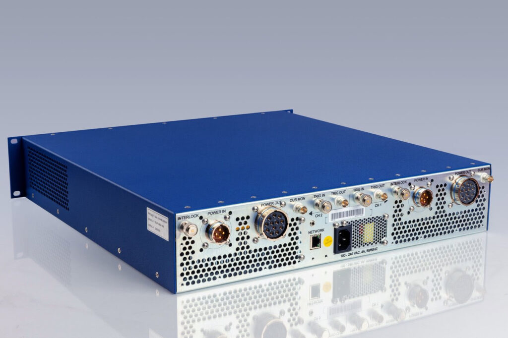
• High-current QCW drivers require robust connectors and low-inductance cabling to the diode array.
• While not part of the driver proper, the connection of driver to array is very important to making the whole work well. Therefore, it is important to specify connector types, cable lengths, and any shielding or isolation requirements early, since these impact both safety and pulse quality.
• This is an important issue, often not addressed adequately by laser engineers. With proper cabling and connector design, the limits of the laser can be pushed much harder. For example, with a 375V array being pumped at 300A with high value di/dt, systems with high-inductance cabling can fail quickly. Even with low inductance cabling systems can fail without mitigation designed in.
Mechanical and Integration Considerations
Beyond electrical performance, mechanical and integration details can significantly affect project risk and time-to-market.
• Form factor and mounting: Decide whether you need a rack-mount unit, benchtop instrument, or OEM module. The mechanical envelope must fit within your laser system, with adequate airflow and access for service.
• Cooling: Some drivers rely on forced-air cooling, while others may require liquid cooling. Confirm the driver’s cooling needs and ensure they align with the thermal design of the overall system.
• EMI/EMC: High di/dt and dv/dt pulses can generate electromagnetic interference. If your system operates in sensitive environments or must meet regulatory standards, include EMI/EMC requirements in the driver specification (filtering, shielding, grounding strategy).
Engaging with the driver vendor early on mechanical and integration topics helps avoid last-minute redesigns when you discover that the unit does not physically or thermally fit your system constraints.
Working with Cutting Edge Optronics
Cutting Edge Optronics provides QCW diode arrays, laser modules, and related components that are widely used in demanding applications. When specifying a driver for CEO arrays, it is advantageous to involve both the array manufacturer and the driver vendor in the requirements process.
• Use the array datasheet as the primary electrical reference: Forward voltage curves, recommended operating current, and environmental limits from the array datasheet should guide the driver specification.
• Request application notes: CEO and other manufacturers frequently publish application notes or integration guides that describe recommended drive conditions, pulse shapes, and cooling strategies. These documents often contain practical limits and configuration examples not obvious from the raw datasheet.
• Share system-level requirements: If your laser must meet specific pulse energy, beam quality, or reliability targets, communicate these to both suppliers. They may propose driver features such as advanced monitoring, internal diagnostics, or redundant protection paths that help achieve the overall system goals.
Checklist for Specifying a QCW Diode Array Driver
To turn the concepts above into an actionable specification, laser engineers can use the following checklist:
1. Define the QCW operating envelope – Peak current, forward voltage, pulse width range, repetition rate, and maximum duty cycle.
2. Set electrical performance requirements – Current regulation accuracy, rise/fall time, pulse shape, timing jitter, and control interface.
3. Quantify thermal and reliability constraints – Average electrical power, junction temperature limits, derating behavior, and required protection features.
4. Address mechanical and integration details – Form factor, mounting scheme, connectors, cabling, cooling, and EMI/EMC considerations.
5. Align with supplier guidance – Use Cutting Edge Optronics array datasheets and application notes as the base reference, and cross-check with driver vendor documentation and industry best practices.
Capturing these elements in a formal driver specification document makes it easier to compare vendor proposals, conduct design reviews, and validate the final system against requirements.
Conclusion
Specifying a laser diode driver for QCW diode arrays is not a purely electrical exercise; it is a system-level design task that touches thermal management, safety, reliability, and integration. By starting from the characteristics of the QCW array—such as those offered by Cutting Edge Optronics—and translating them into concrete driver requirements, laser engineers can ensure that the electrical drive, cooling, and protection strategy all support the desired optical performance and lifetime.
When evaluating drivers, resist the temptation to focus only on headline peak current and voltage ratings. Instead, look closely at current regulation, pulse control, protection features, and how well the driver integrates into your mechanical and safety architecture. Combining vendor datasheets, application notes, and broader industry references yields a robust specification that minimizes risk and maximizes performance.
As QCW diode arrays continue to enable higher peak powers and more compact solid-state laser designs, careful driver selection will remain a differentiating factor for Cutting Edge Optronics’ customers. A well-specified QCW driver can turn a capable diode array into a reliable, high-performance laser subsystem.
Approved for Public Release: NG26-1714 Northrop Grumman © 2026 Cutting Edge Optronics, Inc