High peak power optical pulses are very desirable in industrial, scientific, and military applications.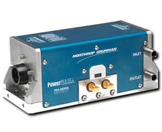 However, maximum peak powers are limited by the damage threshold of the optical materials used and the amount of amplification available. While pulse-pumped amplifiers can achieve high gains, they are typically limited in total average power. Practical pulse trains contain pulses that are 10s of picoseconds in width, repeat every microsecond or faster, and have pulse bursts lasting 1-5ms or longer. Under these conditions a higher average power is needed to sustain the amplification of the pulse train.
Northrop Grumman Cutting Edge Optronics has developed a line of laser amplifiers that have the high gain of the pulse pumped amplifiers, and can maintain the amplifier gain for 1-5ms. This allows the amplification of long pulse trains using fewer devices, less gain material, and lower overall cost.
© 2011 Northrop Grumman Systems Corporation – All Rights Reserved
G. Jay Doster, Ph.D. and Ryan Feeler, Ph.D.
Northrop Grumman Cutting Edge Optronics, 20 Point West Blvd., St. Charles, MO USA 63301
1. INTRODUCTION
Many laser applications require very high peak powers at high repetition rates. The pulses are typically generated from mode-locked laser oscillators, fiber laser oscillators, or modulated CW fiber lasers. Amplifying these pulses to useable peak powers can be challenging as the typical seed laser sources require gains of 30dB or more. In order to obtain high gains in laser amplifiers, high pump powers are required. Continuous operation at high pump powers can limit operational lifetime of the amplifiers and can fracture the gain medium in extreme circumstances. Operation of the amplifiers in quasi-CW mode allows high pump powers without the negative thermal effects seen in the CW pumped case.
Northrop Grumman Cutting Edge Optronics (NGCEO) has developed a line of laser amplifiers specifically for high-energy, quasi-CW operation. The PowerPULSETM laser amplifiers can operate at high pump powers for pumping times on the order of milliseconds. This allows high amplification factors over longer times at lower thermal loads than is available with flash lamp pumped systems. These amplifiers have been used in a wide range of applications, including combustion diagnostics, Optical Parametric Chirped Pulse Amplification (OPCPA), and fundamental physics and chemistry experiments.
If the application allows, the pulses from the seed laser can be chopped into a series of ‘macro-pulses’, each of which contains a sequence of optical pulses at the repetition rate of the seed laser. This concept is illustrated in Figure 1.
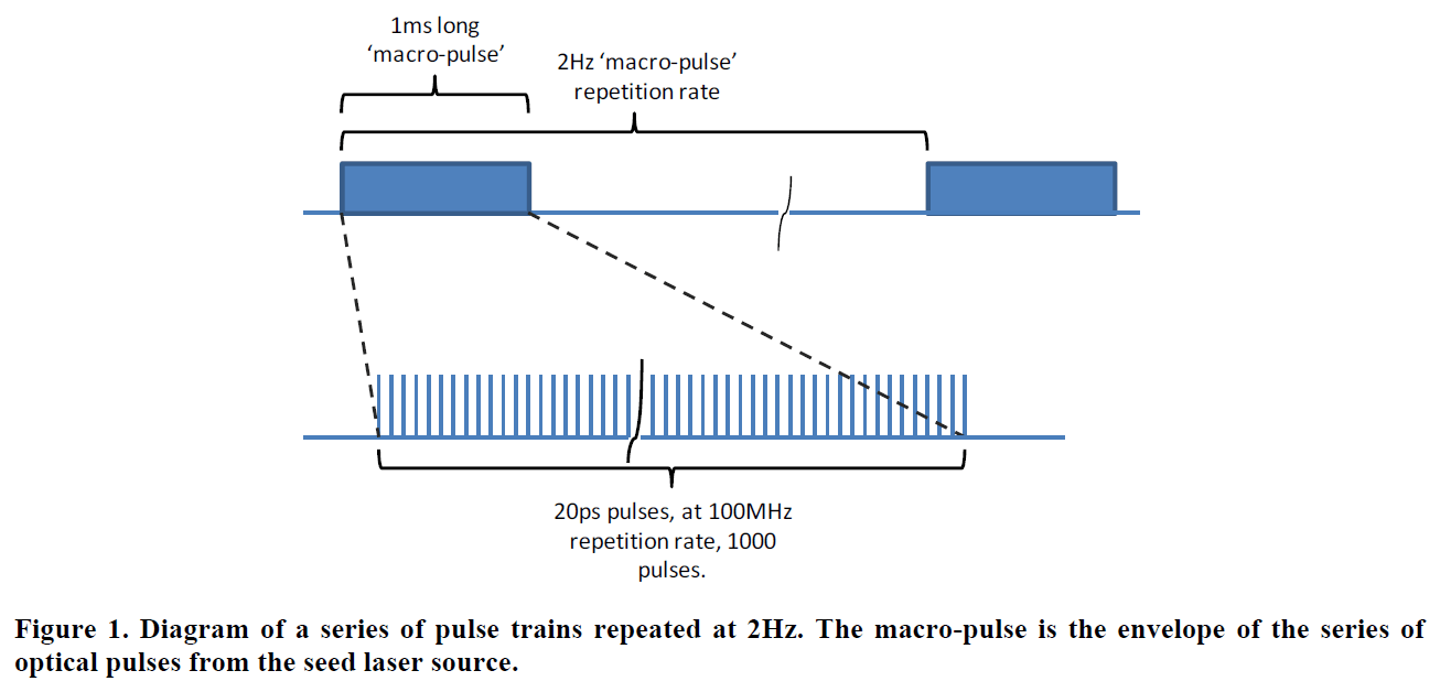 The optical pulse train illustrated above typically repeats at 1-5Hz with the macro-pulse ranging from 1-5ms in length. Amplification of these types of pulses requires systems that can operate at high average powers and create large amplification factors.
Modeling of the laser amplifiers is critical for system design. Tradeoffs of amplifier pump time, pump vs. input pulse phasing, multi-pass architectures, and management of the gain between stages can all be simulated. Simulation of arbitrary pulse trains and amplifiers allows correct system design and minimizes time to ‘first light’. Using a relatively simple model, as discussed below, is sufficient to perform initial design surveys, make system level tradeoffs, and select the proper PowerPULSE amplifier.
2. LASER AMPLIFIERS
Laser amplifiers are the basic building block of any laser system. For the discussion in this technical note, the amplifiers are based on Nd:YAG gain materials with laser diode bars providing the optical pump energy. The amplifiers employ a side pumped rod geometry with both the rod and the laser diode bars water cooled. Rod sizes are available from 2mm to 15mm and optically pumped lengths of 30mm to 170mm. Stored energies of over 4 Joules and repetition rates of over 1 kHz are attainable.
Typical applications for PowerPULSE laser amplifiers involve the amplification of single pulses at repetition rates of 1kHz or less. In this regime the module is optically pumped for 150-250μs. The amount of amplification or gain can be predicted by modeling the laser dynamics of the system. A useful model of the laser dynamics for a four level laser can be created by considering the population level of the excited state of the crystal. The number of atoms in the excited state (n) increases as the pump rate (Wp) is increased and is decreased by the spontaneous emission of the excited atoms. This action is summarized in the following equation:
 Here ntot is the total number of active ions and τf is the fluorescence life time of Nd in the YAG host (240μs). Here it is assumed that the input optical pulse is short with respect to the pumping time. Once the upper level population is known, the small signal gain coefficient (g0) can be found by
![]() Where σ is the emission cross section for Nd:YAG (2.6e-19 cm2). The stored energy (Estored) follows from g0 as
Where σ is the emission cross section for Nd:YAG (2.6e-19 cm2). The stored energy (Estored) follows from g0 as
![]() where hν is the energy per photon at the lasing wavelength. Using calculated stored energy and the energy of the input beam, the output energy of the laser amplifier can be found by
where hν is the energy per photon at the lasing wavelength. Using calculated stored energy and the energy of the input beam, the output energy of the laser amplifier can be found by
 Here Ein and Eout have units of J/cm2, l is the length of the amplifier and Es is the saturation fluence of the gain material (0.667 J/cm2 for Nd:YAG).
In this operational regime, each laser pulse is amplified by a separate pumping event. For a multi-pass system, the remaining upper state population is found after each pass and the resultant g0 is found. The new g0 is used to find the energy output of the latest pass. After enough passes or sufficient input fluence, the amplifier is fully saturated and contributes no more gain to the input beam. Losses due to diffraction, surface reflections, and scatter are not considered in this simplified model.
3. PULSE TRAIN AMPLIFICATION AND MODELING
For laser sources that contain a series of pulses, the modeling is slightly different. In this regime the laser pulses are all amplified by a single pumping event. This means that the individual pulses of the train will be influenced by the earlier pulses. The first pulse in the pulse train will remove some of the stored energy from the amplifier. There may or may not be sufficient time for the amplifier to restore the stored energy before the next pulses pass through the module. As such the next pulse will experience a smaller stored energy and thus a lower gain.
Free Engineering Consultation>>
Since there is now a single pumping event, the model should solve the population equation by integrating from the beginning of the pump until the first pulse arrives as the amplifier. The pulse removes the amount of stored energy as found from Equation 4. The pulse is assumed to be short enough that the pumping during the pulse is not considered. A new value for the population inversion is found from the reduced stored energy. The population equation is integrated with the new initial population condition until the next pulse and the entire modeling cycle is repeated for the entire pulse train.
Using this simulation architecture, the overall gain of the laser amplifier for the entire pulse train can be predicted and the pulse to pulse dynamics can be explored. Since each pulse in the train has a ‘memory’ of the previous pulses, the pulse train can have uneven amplification. This effect for unsaturated amplifiers is illustrated in Figure 2.
 The first graph is a simulation of a 20kHz pulse train passing through a small amplifier where the first pulse in the train arrives at the beginning of the pump pulse. The buildup of the gain can be seen as the pulse train increases in size. The second graph illustrates the results when the pump pulse starts 240μs before the arrival of the first pulse of the train. In this case there is stored energy in the first pulse but steady state gain has not yet been achieved. The third graph represents the pump pulse preceding the pulse train by 420μs. Since each output pulse has the same energy, the amount of stored energy removed from the laser exactly balances the amount of energy increase due to the pumping between each pulse. The last graph is the results when the pump pulse precedes the pulse train by 1ms. In this case the stored energy is higher than the preceding cases and the first pulse sees a large gain. The gain is depleted by the first few pulses at a greater rate than it is replenished by the pump pulse. The phasing of the pump pulse and the pulse train is critical to obtaining constant output energy per pulse.
4. APPLICATIONS
A typical pulse train amplifier system is illustrated in the Figure 3 below. This system is designed to amplify a mode-locked, 10ps, 400MHz pulse train that has a macro-pulse duration of 1.2ms. The entire pulse train repeats at 2Hz. The amplified pulse is designed to be injected into a buildup cavity in order to obtain more than 5MW peak power. The laser source delivers about 0.5W power in 1ms and has a peak power of about 125W. This equates to 0.5mJ per pulse.
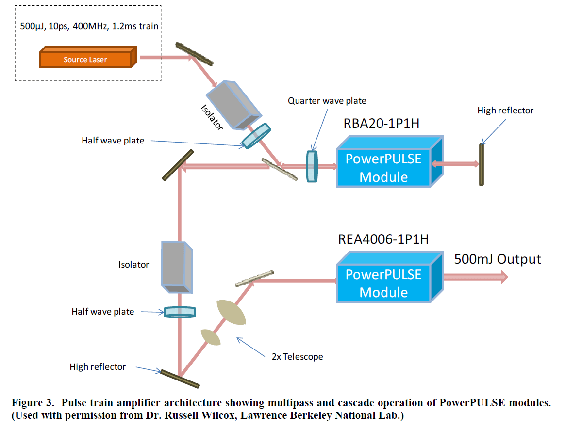 The first stage, RBA20 amplifier is designed to have a two-pass gain of about 100, or a single-pass gain of 10. After the first stage, the beam has about 50W average power (50mJ per pulse). The larger REA4006 amplifier is single-passed for an additional 4x amplification giving 200W output power. The final beam amplification is 400x and the output has 200mJ per pulse. The system as described is capable of over 500mJ per pulse when operated at the maximum pump current limit. In this design the final amplifier is not fully saturated. Another pass of this amplifier would result in an additional 200mJ of energy.
5. INDUSTRIAL SUITABILITY
PowerPULSE amplifiers are based on the same basic design that NGCEO has used for its CW-pumped products for over 15 years. The CW modules are manufactured in high volume and are currently being used in thousands of industrial installations around the world in a variety of applications, with product lifetimes measured in the tens of thousands of hours.
Free Engineering Consultation>>
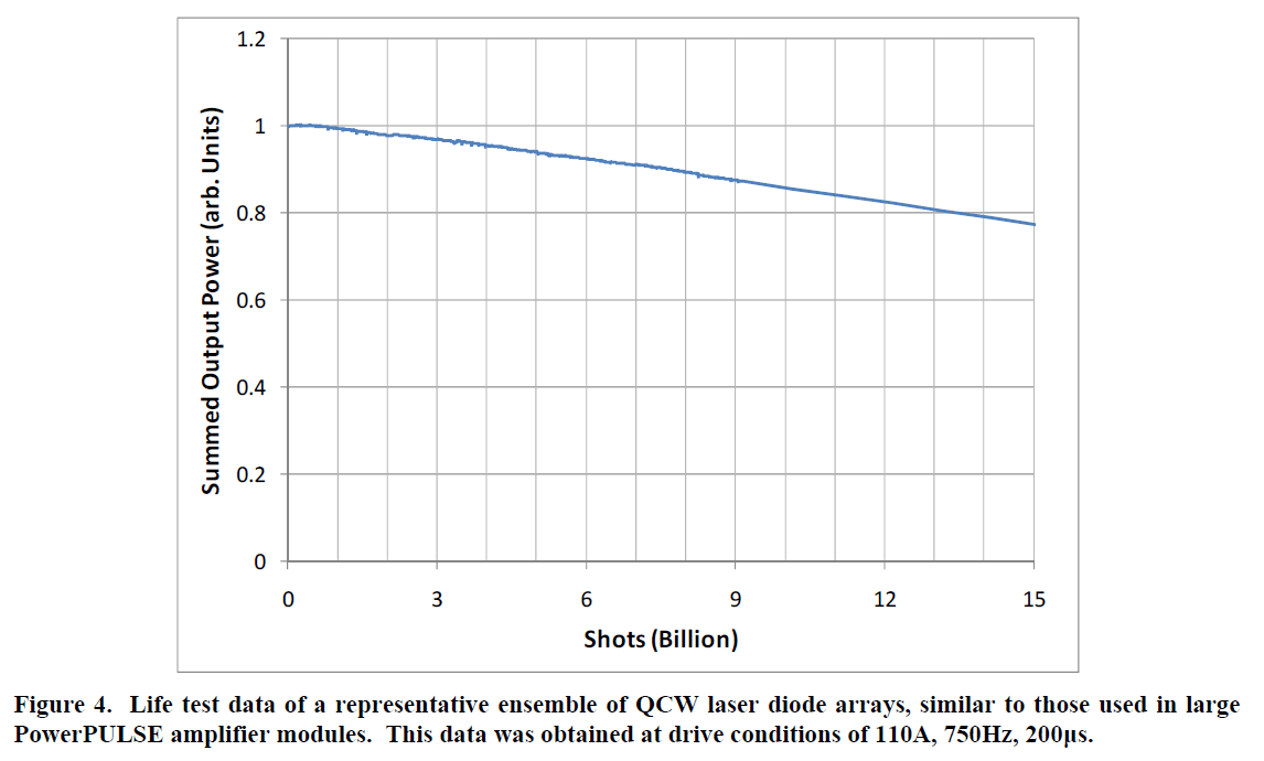
QCW versions of these amplifiers require a higher level of engineering to achieve similar levels of reliability due to the high drive currents and the number of laser diode bars in each module. The PowerPULSE amplifiers that are used in very high-energy systems contain multiple laser diode arrays, resulting in a total bar count of between 20 and 300. Example degradation data for an ensemble of laser diode arrays is shown in Figure 4, and represents what would be expected from a typical PowerPULSE amplifier. Product lifetimes in the tens of billions of shots are typical, and higher shot counts are achievable at derated operating currents. Further details of the life test are available in previous published work [3].
6. CONCLUSION
Northrop Grumman Cutting Edge Optronics has developed an amplifier module family that can operate for extended pumping times, on the order of several milliseconds. The longer pump times allow amplification of high repetition rate pulse trains. The high gain, high average power amplifiers – in combination with accurate modeling – allow selection of the correct amplifier model for the desired output characteristics of the system. Correct time phasing of the pump and pulse train is critical for uniform amplification of the pulse train and is dependent on the system architecture.
These amplifiers are based upon proven design principles and contain long-life laser diode bars. As a result, they are suitable for a wide range of industrial and scientific applications.
REFERENCES