A new generation of diode-pumped solid-state lasers has been developed that enables ultra-stable Ti:Sapphire pumping at high energies. We report an injection-seeded, all diode-pumped high-energy Nd:YLF laser system based on a master oscillator power amplifier (MOPA) configuration. The laser produces pulses with over 4 J of pulse energy at 10 Hz, 527 nm, and pulse duration of ~13 ns. The laser is specifically designed to produce a uniform, flat-top beam in the near field.
Details of the laser design are discussed. The master oscillator is an injection seeded electro-optical Q-switched TEM00 mode laser. It produces stable, temporally-smooth laser pulses as the source for the system. The uniformity of the flat top beam is discussed. The pulse energy stability and beam pointing stability are thoroughly investigated and reported. The lifetime test results for the pump diodes are also presented.
Keywords: Laser diodes, quasi continuous wave (QCW) diode-pumped, high pulse energy, Nd:YLF laser, pumping Ti:Sapphire
Faming Xu, Chris Briggs, Jay Doster, Ryan Feeler and Edward Stephens
Northrop Grumman Cutting Edge Optronics,
20 Point West Blvd, St. Charles, MO 63301, USA
1. INTRODUCTION
Flash lamp-pumped high-energy lasers have been in the market for decades. However, there are several known limitations to this technology. First, pumping is inefficient, partly because lamps are inefficient at converting electricity into pump light and produce a lot of unwanted heat. But even more critical, the lamps produce broadband emission throughout the visible and the infrared spectrums. As a result, most of the light is not absorbed by the laser gain material and ultimately serves only to generate more heat in the pump module. This heat is removed by water cooling the laser head. Flash lamp power supplies also tend to be quite large and operate at extremely high voltages.
For many applications, the biggest drawback is the short lifetime of lamps. The flash lamp pumping energy drops by typically 80% after tens of millions shots. When the lamps are replaced, the cavity optics usually requires a slight realignment to maintain a good output mode from the laser. This routine maintenance actually conceals another limitation – their optical alignment tends to drift over time and requires periodic realignment, irrespective of any lamp change. For example, if the laser system is sensitive to 2% pumping power degradation, then the flash lamp-pumped laser needs to be optimized after just a few days of continuous operation at 10 Hz. In addition, the change in laser energy over the course of a few days makes flash lamp-pumped lasers unsuitable for many spectroscopic applications that require pulse energies to remain unchanged over the course of days, weeks, or months.
Laser diodes offer a degradation rate that is 100-1000 times lower than typical flash lamps. With diode pumped high-energy lasers, the laser system downtime and the cost related to maintain the laser system is dramatically reduced. The total cost of ownership of a diode pumped high-energy laser will be lower than its flash lamp-pumped counterpart.
Within the last 10-20 years, high power laser diodes have become highly reliable. Driven by the increasing demands of high-performance, high-power laser pumping sources and direct industrial processing applications, tremendous breakthroughs have been realized in high power semiconductor diode lasers. These achievements are attributed to a combination of the maturity of semiconductor material epitaxy, the optimization of laser waveguide structures, improvements in facet coating technology, and gains in packaging and cooling technologies. With the increase in reliability and the reduction in cost of high power laser diodes, diode pumped high-energy lasers have reached a very competitive position relative to flash lamp-pumped lasers.
As the Ti:Sapphire laser market broadens to include high pulse energy at high frequency, Joule-class green lasers with excellent beam profiles are required as the pump sources. The uniform beam profile of the pump light provides uniform gain distribution in the Ti:Sapphire crystal. Hot spots on the green beam profile will not only distort the gain uniformity but also can cause the damage to the Ti:Sapphire crystals. The pulse-to-pulse energy stability of the pump laser directly impacts the pulse-to-pulse stability of a Ti:Sapphire laser. The long term energy stability of a Ti:Sapphire laser is related directly to the long term energy stability of the pump laser.
In this paper, an all diode-pumped 4J 527 nm Nd:YLF laser for pumping Ti:Sapphire lasers will be systematically demonstrated. First, the performance and reliability of quasi-continuous-wave (QCW) laser diodes as the pump source will be presented. Second, the key parameters of the gain module as the optical amplifier will be discussed. Finally, the laser layout will be introduced and the performance from the master oscillator to the final output will be reported.
2. PERFORMANCE AND RELIABILITY OF NG CEO QCW HIGH PEAK POWER LASER DIODE
NGCEO 80x nm QCW high peak power laser diodes were used as the pump source for the high pulse energy solid state lasers discussed in this work. Typically there are two types of tests used to characterize the performance and reliability of QCW high peak power laser diodes: a step-stress life test and a long term operational life test. For the step-stress life test, three QCW diode bars were packaged in single-bar arrays and placed on the life test station. The drive current was increased from 150 A to 300 A over time. The step-stress life test data is contained in Figure 1. The data demonstrates excellent performance up to 300 A (approximately 300 W). All data was collected at a repetition rate of 250 Hz and a pulse-width of 150 μs.
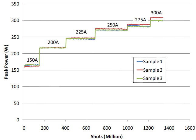
This data is not sufficient to make any claims about expected lifetimes at the given operating currents. However, it does indicate that the material is suitable for low-repetition-rate applications (such as laser range finding) up to a power level of 300 W/bar. In many range finding applications, the product lifetime is in the range of 10-100 million shots. The above test shows that the laser diodes can survive those shot counts with minimal degradation.
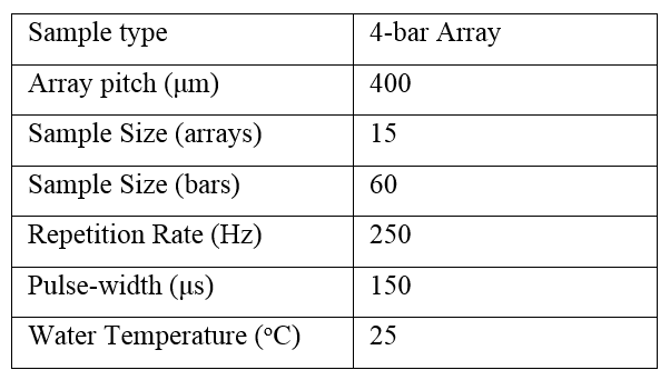
A subsequent operational, long term life test was conducted with an increased sample size. The test parameters are shown in Table 1 below. Since the majority of QCW applications involve multiple bars packaged on tight pitch in order to maximize power densities, 4-bar arrays were selected as the package type for this life test. Therefore the life test represents a good approximation of the potential field use of these diode bars.
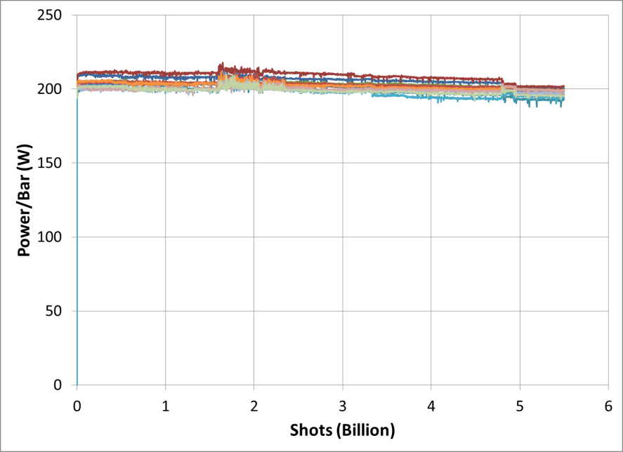
The operational long term life test results are summarized in figure 2. It indicates that there is minimal degradation over the course of the first 5.5 billion shots. As a result, no statistically significant predictions of product lifetime can be made at this point. However this data does represent approximately 255 days of continuous operation under these conditions. Actual operational parameters in a diode-pumped high-energy laser depend on the specific laser design, but the peak power and average power of the laser diode arrays in an NGCEO laser are operated at de-rated conditions when compared to the above life test. Therefore, it is a fairly safe assumption that these devices will survive for over 10 billion shots, which meets one of the key thresholds of industrial operation.
3. GAIN MODULE PARAMETERS AND PERFORMANCE VERIFICATION
A limited number of gain media are suitable for high-energy laser applications. Nd:YAG and Nd:YLF are the most common crystals due to their robustness and availability. Each of these two crystals has its unique advantages and disadvantages.
An Nd:YAG crystal operating at 1064 nm is more robust and homogeneous than an Nd:YLF crystal. Its high stimulated emission cross section results in low stored-energy density still adequate for high frequency operation. Its poor performance under high thermal load, such as a high thermal lensing effect and a high thermally induced stress birefringence, limit the maximum average output power.
An Nd:YLF crystal operating at 1053 nm provides several advantages. First, its high saturation fluence (low-gain cross section) allows working at high laser fluence while minimizing pulse distortion. Second, strong static birefringence practically eliminates the impact of thermally induced stress birefringence, and Nd:YLF has a relatively weak thermal astigmatism. A final practical advantage is that it matches the gain peak of Nd-doped phosphate laser glasses, which permits employing a common front end for both pumping OPCPA systems and seeding large glass amplifiers used in large laser-fusion facilities. The disadvantages of Nd:YLF are the poor transmitted-wave front quality and low thermal fracture limit.
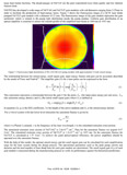
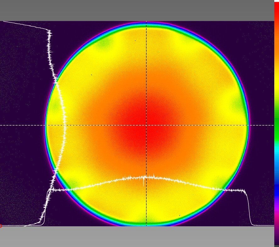
NGCEO has developed a wide range of Nd:YAG and Nd:YLF gain modules with rod diameters ranging from 2-25mm in order to facilitate the production of high-energy lasers. Figure 3 shows the fluorescence image of a QCW laser diode pumped Nd:YLF gain module with a diameter of 22 mm. The fluorescence image of the gain module represents the gain uniformity which is related to the pump light distribution inside the pump module. Uniform gain distribution of an optical amplifier is essential to ensure the smooth profile of the amplified laser beam at 1064 nm or 1053 nm.
The relationship between the stored energy, small signal gain, input energy fluence and gain can be accurately described by the model of Franz and Nodvik[1]. The amplifier gain (G) for a laser pulse can be expressed in the form
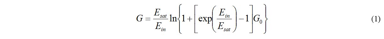
This expression represents a relationship between the gain G for the pulse, Ein (the input pulse energy per unit area), Esat (the saturation energy density) and G0 (the initial small signal gain) where G0 is defined as
 In equation (2), g0 is the SSG coefficient, l is the length of the active medium and Dst is the stored energy density.
For a 4-level system with fast lower level relaxation the saturation fluence is given by
 where h is Planck’s constant, ν is the frequency of the laser wavelength, σ is the stimulated emission cross-section.
The stimulated emission cross section of Nd:YAG2 is 2.8×10⁻¹⁹ cm-2. Thus for the saturation fluence we acquire 0.67 J/cm2. The stimulated emission cross section of Nd:YLF2 is 1.2×10⁻¹⁹ cm-2 at 1053 nm. So the saturation fluence for Nd:YLF is calculated at 1.57 J/cm2. To achieve the good optical-optical efficiency, the power amplifiers should be operated over the saturation fluence.
With the help of this model, the optimal stored energy and the small signal gain can be calculated for each amplification stage for the laser system during the design process. The operational parameters such as the peak pump current and duration and the total number of laser diode bars for each gain module are determined. The small signal gain (G0) of each gain module is measured during the manufacturing process to verify its performance against the theoretical predictions.
4. 4 JOULE 527 NM LASER LAYOUT AND PERFORMANCES
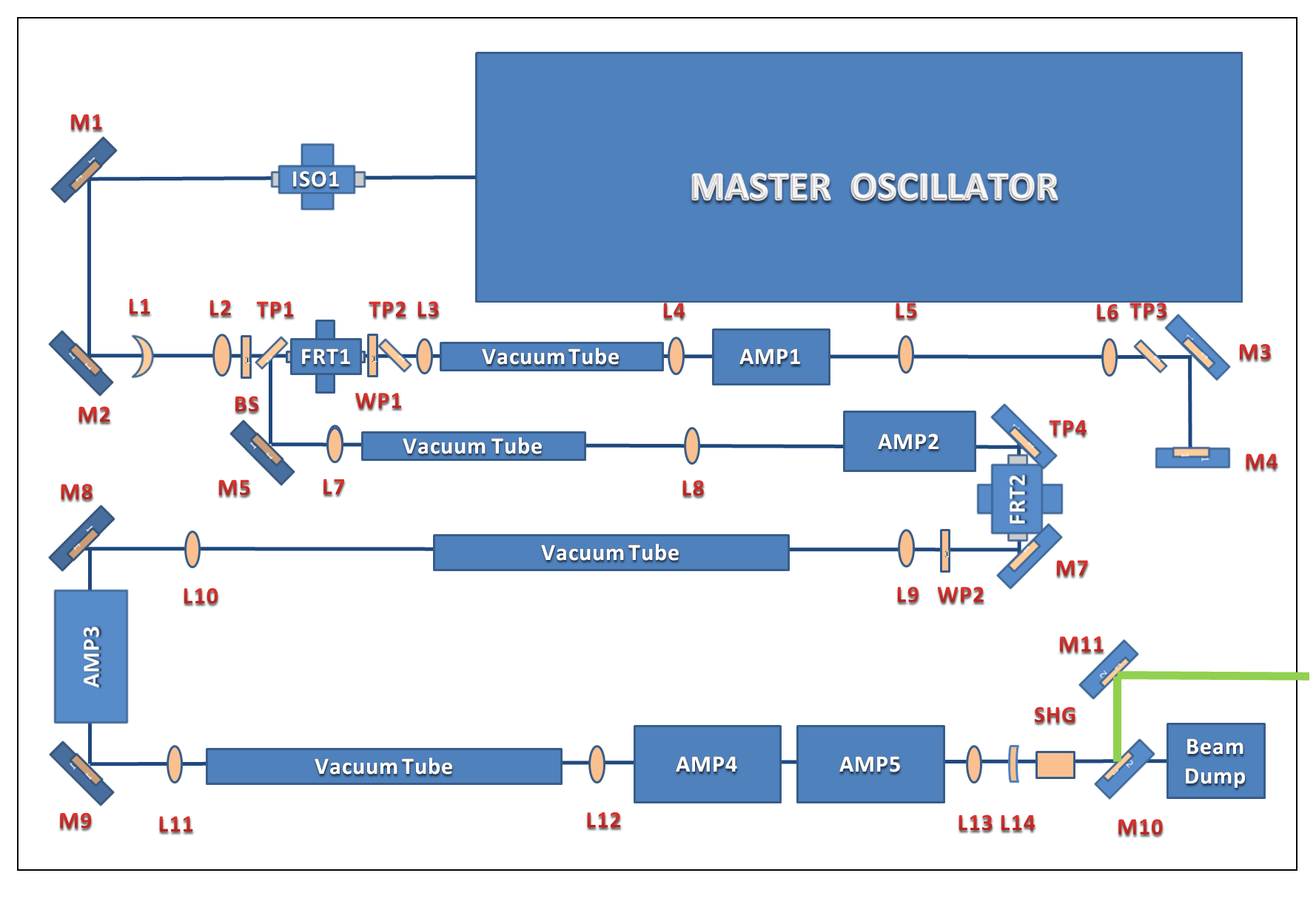
The layout of 4J 527 Nd:YLF laser is illustrated in Figure 4. This all diode-pumped high-energy Nd:YLF laser system was based on a master oscillator power amplifier (MOPA) configuration. The operational parameters and gain modules were predetermined at the design phase per the requirements for the laser. The laser was built on a 4’x6′ optical table. This modular design approach enables us to address different energy levels at different operational frequencies based on the requirements of a given application or customer.
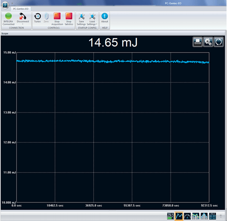
The master oscillator was built using a stable resonator design well-suited for TEM00 operation. The cavity was injection seeded to generate single longitudinal mode output. Two gain modules with 2.5mm rods were used – one in the laser cavity and one immediately after the output coupler as a preamplifier. The pulse energy out of the master oscillator was ~ 15mJ.
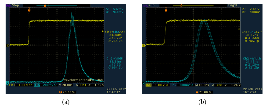
The temporal profiles of the output laser pulse from the oscillator are shown in Figure 5. With injection seeding, the laser had a smooth temporal profile and the delay time was shortened by 50 ns. The jitter with respect to the external trigger was measured below 1 ns RMS.
The long term energy stability of the master oscillator was evaluated and the results are summarized in Figure 6. All laser pulses were measured over a 25-hour period. The calculated energy stability was 0.25% RMS.
In Figure 4, M1 to M9 refer to high reflective mirrors while TP1 to TP4 are 45° thin film polarizers. An isolator (ISO1) was installed immediately after the oscillator to prevent any laser feedback into the oscillator. A thin film polarizer (TP1), Faraday rotator (FRT1), half wave plate (WP1) and another thin film polarizer (TP2) formed the second isolator. A thin film polarizer (TP3) was installed to suppress the light at 1047 nm. A thin film polarizer (TP4), Faraday rotator (FRT2) and half wave plate (WP2) formed another isolator. All these isolators were implemented to prevent damage to the laser from any back-reflections.
Lenses L1 and L2 were used to expand the laser beam. The beam shaper (BS) generated the flat top beam from the Gaussian beam. The smooth flat top beam was relay-imaged to the center of each optical amplifier from AMP1 to AMP5 by the Lenses L3 to L12. A pair of lenses also functioned as the beam expander to fill up the rod with the right diameter of the laser beam.
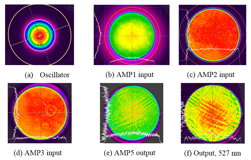
Figure 7 summarizes the beam profiles at several locations of the laser as the laser beam propagated through the system. The fine interference pattern and ring structures on the beam profiles were caused by the optical attenuators and the dust particles on the beam profile measurement setup. It was noticed that some large fringe patterns appeared on the beam profile after the AMP4 was installed, but AMP5 did not cause any further degradation of the beam profile. The degradation of the beam profile after AMP4 is believed to be related to the quality of that particular Nd:YLF crystal. This problem can be addressed with a better quality Nd:YLF rod.
The laser beam double passes the first amplifier AMP1 to boost the pulse energy to approximately 400 mJ. After a single pass through AMP2, the pulse energy was 1.8 J. The pulse energy was measured around 3.8 J after pass AMP3, 6 J after AMP4 and 9 J after AMP5. The pump current for all the amplifiers was limited to 150 A and pulse-width around 350 ms to support over 10 billion shots of lifetime.
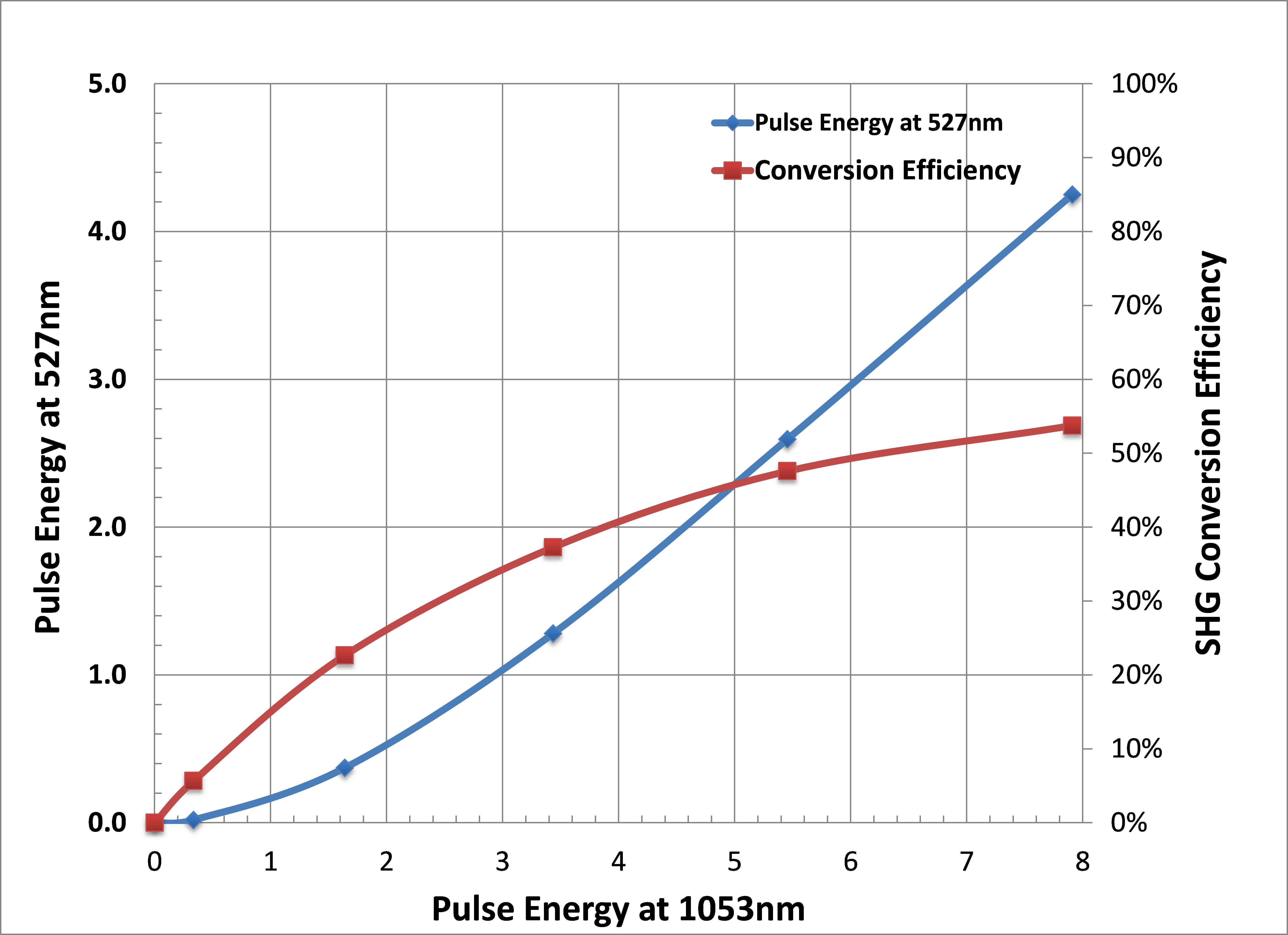
The laser beam size was reduced to approximately 18 mm with lenses L13 and L14 to ensure good SHG conversion efficiency. The smooth flat beam profile was relay-imaged at the middle of SHG crystal. Lastly, two 45° harmonic separation mirrors (M10, M11) guided the horizontally polarized green laser beam through the output window while the remaining IR beam was collected by the water cooled beam dump. The conversion efficiency depended on the input pulse energy with the fixed pulse-width ~20 ns at single longitudinal mode. The results are summarized in Figure 8. A type I 20x20x15mm LBO crystal was used as the SHG. Over 4 J pulse energy at 527 nm was reached with 8 Joule input energy to the SHG crystal. The SHG conversion efficiency was approximately 55% at 4 J output energy at 527 nm.
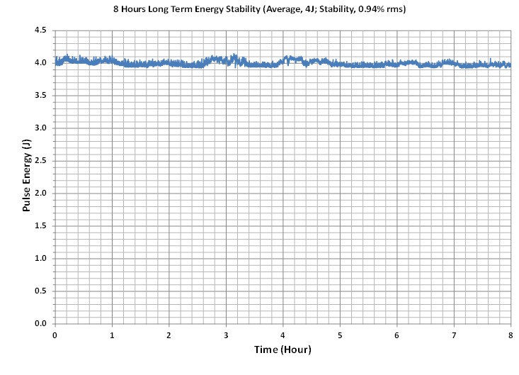
The long term energy stability of the laser at 527 nm was studied. The RMS pulse energy stability was measured to be less than 1% over eight hours. The results are reported in Figure 9 below. The energy variation was mostly due to the overnight ambient temperature change of ~2 degree C. No energy degradation was observed.
5. DISCUSSION AND CONCLUSIONS
An all diode-pumped 4 Joule 527 nm Nd:YLF laser with the smooth flat top beam profile which is ideal for pumping Ti:Sapphire lasers was demonstrated. The laser had overall 21% optical-to-optical efficiency at 1053 nm. The modular design approach opens the door to affordable, customized diode-pumped high-energy lasers.
REFERENCES
[1] Frantz, L. M., J. S. Nodvik. J. Appl. Phys., 1963, 34(8), 2346. [2] W. Koechner, [Solid-State Laser Engineering], Springer, 6th rev. and updated ed., 55-68 (2006).