Ti:Sapphire lasers have become prominent in the field of ultrafast lasers and oscillators due to their broad emission bandwidth and the ability to minimize opto-thermal effects over a wide range of operating parameters. This article examines the construction of a high-power Ti:Sapphire laser from the ground up. Mode-locked lasers are discussed, as are single-pass, multi-pass, and regenerative amplifiers. The use of pulse pickers to help generate higher pulse energies is also discussed.
In order to build high-average-power Ti:Sapphire lasers, high-quality high-average-power green pump lasers are required as pumps for the final amplification stage. This article examines the main requirements on the pump lasers, and also discusses the relative merits of Nd:YAG and Nd:YLF systems.
Ti:Sapphire Laser Overview
Northrop Grumman Cutting Edge Optronics[1], 20 Point West Blvd., St. Charles, MO USA 63301
Introduction
Since its first use in 1986 [1], titanium-doped sapphire (in short: Ti:Sapphire) has become a great workhorse in the area of ultrafast laser oscillators and amplifiers – particularly in the regime of very short pulse durations below 10 fs where few alternative materials are available. Ti:Sapphire has an extremely broad emission bandwidth, allowing the amplification of very broadband ultrashort pulses without much gain narrowing. In addition, the excellent thermal conductivity of sapphire keeps opto-thermal effects at a low level even for pump powers in the multi-watt regime. Since most other broadband laser gain media have relatively poor thermal properties, Ti:Sapphire offers a unique performance for use in ultrafast laser systems.
Another application of Ti:Sapphire, which also utilizes the large emission bandwidth, is in the area of wavelength-tunable lasers. Here, the emission spectrum is usually quite narrow, while its center wavelength can be tuned over a large wavelength range, e.g. by simply turning an adjustment knob. Many such tunable lasers provide continuous-wave emission, but others are Q-switched, gain-switched or mode-locked. In this article, though, we concentrate on ultrafast pulse sources and not specifically on wavelength tuning. We briefly describe Ti:Sapphire-based mode-locked lasers for generating ultrashort pulses and then focus on Ti:Sapphire amplifiers for getting to higher average powers and pulse energies.
The only pronounced disadvantage of Ti:Sapphire is that its pumping requirements are somewhat inconvenient in terms of pump wavelength and beam quality, as is discussed in section 3. Fortunately, pump lasers ideally suited for that purpose are commercially available.
[1] [email protected], (636) 916-4900, www.northropgrumman.com/ceolaser
Architecture of Ultrafast Laser Systems
Mode-locked Laser
In the simplest case, an ultrafast Ti:Sapphire laser system consists only of a mode-locked laser. That has a laser resonator which is often about 187 cm long, such that the round-trip time of pulses circulating in that resonator leads to a common pulse repetition rate of about 80 MHz. Each time the circulating pulse hits the output coupler mirror (one of the two end mirrors), a small portion of its energy transmits that mirror and is obtained as an output pulse.
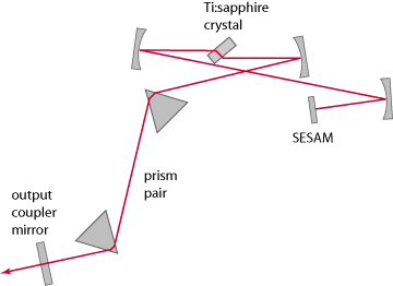
For operation in a steady state, the mode-locked laser must be constructed such that the circulating pulse remains essentially unchanged after each complete round-trip – despite the energy losses and various dispersive, nonlinear and other effects occurring at various optical elements in the resonator. The laser crystal replenishes the pulse energy, while not excessively reducing the spectral width (due to its large gain bandwidth). Some kind of real or artificial saturable absorber (e.g. a semiconductor saturable absorber mirror, SESAM) must start and stabilize the pulse generation, preventing the output of only a continuous wave or some noisy structures. Carefully controlled chromatic dispersion, modified e.g. by using some tailored dispersive mirrors for dispersion compensation, must help to balance the considerable nonlinear effects occurring particularly in the laser crystal. The circulating pulse will typically approach a steady state where it is fully reproduced after each round trip, provided that a stable steady state exists, which is one of the crucial design aspects. Particularly when very short pulse durations below 10 fs are needed, various design issues become rather involved – substantially more than for amplifiers. Partly this is due to various kinds of instabilities which mode-locked lasers can exhibit. The details of designing such mode-locked lasers are rather involved and outside the scope of this article.
Single-pass and Multipass Amplifier with and without Pulse Picker
For a mode-locked Ti:Sapphire laser alone, the average output power is typically limited to at most a couple of watts. The simplest way to improve on that is an additional single-pass amplifier, which amplifies the whole pulse train to a somewhat higher power level. Average powers of more than 10 W are possible, although thermal effects then get more and more severe.
Due to the high pulse repetition rate of e.g. 80 MHz, the pulse energies are still rather small – for example, 10 W average power then corresponds to 10 W / 80 MHz = 125 nJ. For comparison, applications in micromachining typically require many microjoules, as a certain peak power level must be reached; a high average power alone is not sufficient. Therefore, one needs to reduce the pulse repetition rate as explained in the next section.
A pulse picker, consisting of a fast electro-optic modulator, a fast photodetector and suitable driver electronics, allows one to transmit only every Nth pulse and to block all others. This means that the pulse repetition rate is divided by N. Of course, the average power is also reduced at least by that factor, depending on how much of the pulse energy can be transmitted.
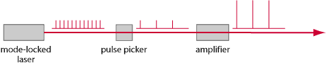
A single-pass amplifier after the pulse picker can then be used to increase the pulse energy and average power. Since for a solid-state laser amplifier only the average power (and not the pulse energy) determines the strength of gain saturation, the power amplification factor achieved with a given pump power can be much larger if the pulse repetition rate is strongly reduced. Therefore, one can obtain accordingly higher pulse energies.
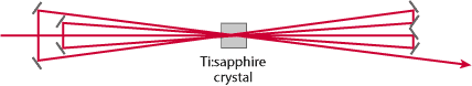
As an example, consider an 80-MHz laser with 1 W average output power, corresponding to 12.5 nJ. A single-pass amplifier may directly boost the average power to 5 W, obtaining 62.5 nJ. If the repetition rate is first reduced by a factor 4 to 20 MHz, 5 W of average power implies a pulse energy of 250 nJ. However, amplifying from 1 W / 4 = 250 mW to 5 W requires an amplifier gain factor of 20 (corresponding to 13 dB), which is quite high for a single-pass amplifier. One may therefore need multiple passes through the amplifier. For example, one can use a set of mirrors to obtain several passes under slightly different directions. For amplifier gains far above 10 dB, the multipass approach is no longer practical. In that regime, one has to use some other approach, such as a regenerative amplifier.
Regenerative Amplifier
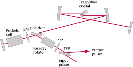
A regenerative amplifier has a kind of laser resonator, where a pulse can circulate as in a mode-locked laser. However, an input pulse is injected from some other source (typically, from a mode-locked laser after a pulse picker) into the amplifier’s resonator. The laser pulse then undergoes a large number of round trips (e.g. 50-100), and is finally coupled out. Pulse injection and extraction can be done with two fast optical switches (typically, electro-optic modulators) or with a single one. It is crucial that the switch operation is precisely synchronized with the input pulse source and for extraction with the round trips. Fast photodetectors provide the inputs for suitable drive electronics.
With that approach, the achievable gain is virtually unlimited, as one may realize a large number of round trips. In practice, the input pulse energy should not be too small in order to avoid problems with noise, and sometimes to avoid problems with bifurcations and chaos in certain regimes. It is reasonable, for example, to start with 10 nJ and amplify that to 1 mJ, which means an overall gain as high as 50 dB. If the pulse repetition rate is low enough – e.g. 1 kHz – , 1 mJ correspond to 1 W average power, which is readily achievable.
Some amount of nonlinear and dispersive effects can be tolerated without getting excessively distorted output pulses. In some cases, the effect of gain filtering is compensated by adding an intracavity filter which somewhat attenuates the central part of the spectrum; this results in a larger output bandwidth at the expense of a reduced efficiency.
Very high average powers of >10 W are more difficult to achieve in regenerative amplifiers than in single-pass devices. Therefore, one may combine a regenerative amplifier, providing most of the required gain and a moderate average output power, with a multipass amplifier which provides e.g. 5 or 10 dB additional gain at the required high output power level. However, one can also get dozens of watts directly from a regenerative amplifier when using a cryogenically cooled laser crystal – see e.g. Ref. [11].
Note that regenerative amplifiers can exhibit certain instabilities, involving phenomena like period doubling and chaos. The origin of such problems is the fact that the residual stored energy in the laser crystal after an amplification cycle can influence the next cycle. Whether stable operation is achieved depends on a number of parameters, including the pulse repetition rate, the pump power and the input signal energy. Numerical simulations are suitable for analyzing this aspect.
Additional Means for Pulse Management
Ultrashort pulses can have enormous peak powers even if the pulse energy stays moderate. For example, a Ti:Sapphire amplifier system may easily reach a pulse energy of 1 mJ, which for a pulse duration of 10 fs results in a peak power of nearly 100 GW (dependent on the exact pulse shape). This kind of peak power applied to the typically quite small mode areas leads to enormous optical intensities, which can give rise to a number of nonlinear effects or even optical damage.
In addition to nonlinear effects, the large optical bandwidth of ultrashort pulses makes them sensitive to chromatic dispersion. Essentially, one obtains frequency-dependent phase shifts – but not just in proportion to the absolute frequency, as for a simple non-dispersive delay line: there can in general be a complicated nonlinear dependence of phase shifts on the optical frequency. That is related to a frequency-dependent group velocity: different spectral parts of the pulses experience difference time delays e.g. when circulating in a regenerative amplifier. As a result, pulses can get temporally broadened or compressed, and also strongly distorted.
There are a substantial number of methods for keeping such effects under control. Typically, they involve the introduction of additional dispersive elements. Dispersion compensation in the context of mode-locked lasers has been discussed previously, but dispersive elements are also used within and between amplifier stages. Two typical approaches are briefly described in the following:
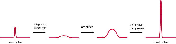
Chirped-pulse amplification [6] means that one substantially increases the pulse duration within one or several amplifier stages with some strongly dispersive element before the amplifier. The stretched (and chirped) pulses have an accordingly lower peak power, so that nonlinear effects are avoided or at least mitigated. After the amplifier, essentially the opposite dispersion is applied in order to temporally compress the pulses again. Figure 5 shows a schematic setup.
In some cases, some degree of temporal pulse broadening is achieved in the amplifier itself, resulting from normal dispersion of the amplifier’s components and also the Kerr effect (the dominant nonlinear effect). In the normal dispersion regime, one obtains both temporal and spectral broadening while avoiding wave-breaking effects. (The latter are frequently encountered in the anomalous dispersion regime and are avoided if possible as they make subsequent pulse compression difficult.) After the amplifier, one again applies a dispersive compressor (with anomalous dispersion) in order to obtain very short output pulses.
Depending on the required pulse energy and duration, and on other boundary conditions such as required pulse quality and compactness of the device, some suitable scheme for managing dispersive and nonlinear effects has to be implemented.
Pump Laser Requirements
Pump Lasers for Mode-locked Ti:Sapphire Lasers
As discussed in the introduction, the Ti:Sapphire gain medium combines some ideal features particularly for ultrashort pulse generation. A disadvantage, however, is that the requirements on the pump laser are quite high.
One aspect is the required short pump wavelength, which should ideally be in the green spectral range. In addition, Ti:Sapphire needs to be pumped with fairly high intensities. That is essentially a consequence of its small s–t product: a combination of moderately large emission cross-sections and a short upper-state lifetime implies a high saturation intensity (of the order of 200 kW/cm2), so that high average laser intensities (order of 1 MW/cm2) and correspondingly high pump intensities are needed. That means that one needs to use a strongly focused pump beam. For a mode-locked laser with a few hundred milliwatts of output power, for example, the pump beam radius needs to be of the order of 20 µm only. As that small beam size has to be maintained over typically several millimeters of crystal length, the pump beam quality has to be fairly high: even for diffraction-limited beam quality, the Rayleigh length of a 532-nm beam with 20 µm focus beam radius has a Rayleigh length of only ~4 mm in the crystal.
Note that in case that soft aperture Kerr lens mode locking is used in an ultrafast laser, the pump beam profile has to be even somewhat smaller than the laser beam profile.
In any case, a pump source with close to diffraction-limited beam quality is clearly ideal, if not even strictly required, as one then obtains a very stable beam profile with approximately Gaussian shape. Note that any changes of pump beam profile could affect the laser beam position and size, and that could have detrimental effects.
Although there has been some progress with green-emitting laser diodes, we are far from routinely using those for Ti:Sapphire lasers and amplifiers, particularly when high powers are required. Even for the more convenient near-infrared spectral region, diffraction-limited operation with multi-watt output powers is difficult to achieve with diode lasers, and for the green and blue spectral region this holds even more. Only very low output powers are possible with direct diode pumping [2].
Currently, one typically pumps a Ti:Sapphire laser or amplifier with a system which is based on a diode-pumped Nd:YAG or Nd:YVO4 laser and a frequency doubler for generating green light. Neodymium-based solid-state lasers can easily give diffraction-limited infrared output with tens of watts, and an intracavity frequency doubler in a continuous-wave laser can convert much of that power to a green output beam, if infrared output coupling is minimized. The high beam quality of the infrared laser remains essentially preserved in the frequency doubling process if the system is properly designed.
Pump lasers for mode-locked solid-state lasers always work in continuous-wave operation. There is no need to synchronize the pump power with the generated pulses, as the upper-state lifetime of the gain medium is orders of magnitude longer than the round-trip time of the pulses, and the energy of the circulating pulse is far below the saturation energy.
It is desirable to have low power fluctuations in the pump beam, particularly at frequencies of the order of the relaxation oscillation frequency (some hundreds of kilohertz) and below. As a mode-locked laser contains some kind of saturable absorber, which reduces the damping of relaxation oscillations, pump power fluctuations have an increased impact on the laser noise. They will not only lead to fluctuations of pulse energy, but also affect other quantities such as the pulse duration and chirp.
Pump Lasers for Ultrafast Amplifiers
For pulsed amplifier systems, the requirements on the pump source are different in some respects.
For systems with a low pulse repetition rate (e.g. ~ 1 kHz), a pulsed pump source is required, which is synchronized with the pulses to be amplified. This is because the upper-state lifetime of a Ti:Sapphire crystal (about 3.2 µs) is much shorter than a pulse spacing of ~ 1 ms. Continuous-wave pumping would only be appropriate for extremely high pulse repetition rates (many hundreds of kilohertz).
For pulsed operation, a Q-switched neodymium-based infrared laser supplemented with a frequency doubler is usually the only option. (Diode pumping is even farer from reality in the pulsed regime, as diode lasers cannot produce short high-energy pulses.) Such a system often (but not always) uses an extra-cavity frequency doubler instead of one within the resonator.
Typical laser gain media for such pump lasers are Nd:YAG and Nd:YLF. These can store relatively large amounts of energy, which one can then easily extract within 100 ns or less. Nd:YLF, having a long upper-state lifetime of 480 µs, is particularly suitable for low repetition rates (e.g. 1-3 kHz), whereas Nd:YAG is otherwise often preferred. (In many cases, however, both media are similarly suitable.) The pulse duration is not critical, as it is anyway far below the upper-state lifetime of Ti:Sapphire. The r.m.s. timing jitter should also be far below that upper-state lifetime, which is easy to achieve.
The pump power required for a final amplifier stage may be substantially higher than for a mode-locked laser, as the average output power may be several watts instead of well below 1 W. On the other hand, the pump intensities used are roughly the same as for lower-power devices. This means that the pump beam of a high-power device does not have to be focused as tightly, and the beam quality can be correspondingly lower. Depending on the case, an M2 value of 10 or 20 may be sufficient. Still, it is desirable that the pump beam shape does not undergo strong changes, i.e., remains stable over time.
Bibliography
[1] P. F. Moulton, “Spectroscopic and laser characteristics of Ti:Al2O3”, J. Opt. Soc. Am. B 3 (1), 125 (1986)
[2] P. W. Roth et al., “Directly diode-laser-pumped Ti:sapphire laser”, Opt. Lett. 34 (21), 3334 (2009)
[3] A. Stingl et al., “Sub-10-fs mirror-dispersion-controlled Ti:sapphire laser”, Opt. Lett. 20 (6), 602 (1995)
[4] D. H. Sutter et al., “Semiconductor saturable-absorber mirror-assisted Kerr lens modelocked Ti:sapphire laser producing pulses in the two-cycle regime”, Opt. Lett. 24 (9), 631 (1999)
[5] U. Morgner et al., “Sub-two cycle pulses from a Kerr-lens mode-locked Ti:sapphire laser”, Opt. Lett. 24 (6), 411 (1999)
[6] D. Strickland and G. Mourou, “Compression of amplified chirped optical pulses”, Opt. Commun. 56, 219 (1985)
[7] M. Lenzner et al., “Sub-20-fs, kilohertz-repetition-rate Ti:sapphire amplifier”, Opt. Lett. 20 (12), 1397 (1995)
[8] S. Backus et al., “Ti:sapphire amplifier producing millijoule-level, 21-fs pulses at 1 kHz”, Opt. Lett. 20 (19), 2000 (1995)
[9] S. Backus et al., “High power ultrafast lasers”, Rev. Sci. Instrum. 69 (3), 1207 (1998)
[10] J. Seres et al., “Sub-10-fs, terawatt-scale Ti:sapphire laser system”, Opt. Lett. 28 (19), 1832 (2003)
[11] I. Matsushima et al., “10 kHz 40 W Ti:sapphire regenerative ring amplifier”, Opt. Lett. 31 (13), 2066 (2006)
[12] D. M. Gaudiosi et al., “Multi-kilohertz repetition rate Ti:sapphire amplifier based on down-chirped pulse amplification”, Opt. Express 14 (20), 9277 (2006)
[13] Z. Wang et al., “High-contrast 1.16 PW Ti:sapphire laser system combined with a doubled chirped-pulse amplification scheme and a femtosecond optical-parametric amplifier”, Opt. Lett. 36 (16), 3194 (2011)
Approved for Public Release 14-0554
© 2014 Northrop Grumman Systems Corporation – All Rights Reserved