Ti:sapphire lasers have become prominent in the field of ultrafast oscillators and amplifiers due to their broad emission bandwidth and the ability to minimize opto-thermal effects over a wide range of operating parameters. In order to build high-average-power Ti:sapphire lasers, high-quality high-average-power green pump lasers are required.
The performance of CEO pump lasers is examined in this work, particularly the 50 mJ Patara™-HP50 YLF and 200 W Patara-HP200 YAG lasers. Analysis of pulse energy performance over repetition rate is presented, as is a summary of the beam quality, optical pulse, and long-term power stability. A discussion of reliability is also included.
Pump Lasers for Ultrafast Amplifiers
Faming Xu, Ph.D.[1], G. Jay Doster, Ph.D. and Ryan Feeler, Ph.D.
Northrop Grumman Cutting Edge Optronics, 20 Point West Blvd., St. Charles, MO USA 63301
INTRODUCTION
Titanium-doped sapphire (in short: Ti:sapphire) has become a great workhorse in the area of ultrafast laser oscillators and amplifiers – particularly in the regime of very short pulse durations below 10 fs, where hardly any alternative materials are available. Ti:sapphire has an extremely broad emission bandwidth, allowing the amplification of very broadband ultrashort pulses without much gain narrowing. In addition, the excellent thermal conductivity of sapphire keeps opto-thermal effects at a low level, even for pump powers in the multi-watt regime. As most other broadband laser gain media have relatively poor thermal properties, Ti:sapphire offers a unique performance for use in ultrafast laser systems.
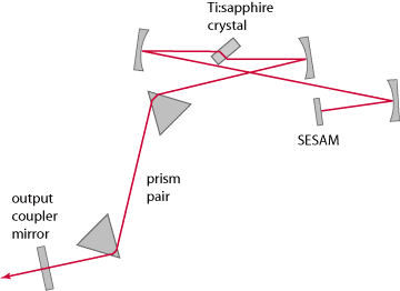
In the most basic case, an ultrafast Ti:sapphire laser system consists only of a mode-locked laser. That has a laser resonator which is often about 187 cm long, such that the round-trip time of pulses circulating in that resonator leads to a common pulse repetition rate of about 80 MHz. Several methods of mode-locking are available, including use of a semiconductor saturable absorber mirror (SESAM) or Kerr-lens mode-locking. The cavity also includes some means of compensating for dispersion in the crystal in order to maintain the short pulse: either chirped mirrors or a prism pair. Each time the circulating pulse hits the output coupler mirror (one of the two end mirrors), a small portion of its energy transmits that mirror and is obtained as an output pulse. Figure 1 shows a schematic setup.
With a mode-locked Ti:sapphire laser alone, the average output power is typically limited to at most a couple of watts. The simplest way to improve on that is an additional single-pass amplifier, which amplifies the whole pulse train to a somewhat higher power level. Average powers of more than 10 W are possible, although thermal effects then get more and more severe.
As an example, consider an 80 MHz laser with 1 W average output power, corresponding to 12.5 nJ. A single-pass amplifier may directly boost the average power to 5 W, obtaining 62.5 nJ. If the repetition rate is first reduced to 4-20 MHz, 5 W already implies 250 nJ. However, amplifying from 1 W / 4 = 250 mW to 5 W already requires an amplifier gain factor of 20 (corresponding to 13 dB), which is quite high for a single-pass amplifier. One may therefore need multiple passes through the amplifier. For example, one can use a set of mirrors to obtain several passes under slightly different directions.
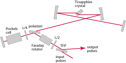
For amplifier gains far above 10 dB, the multipass approach is no longer practical. In that regime, one has to use a regenerative amplifier approach. A regenerative amplifier (Figure 2) is configured as a laser resonator, where a pulse can circulate as in a mode-locked laser. An input “seed” pulse to be amplified is injected from some other source (typically, from a mode-locked laser after a pulse picker) in to the amplifier’s resonator, then undergoes e.g. 50 or 100 round trips, and is finally coupled out.
With that approach, the achievable gain is virtually unlimited, as one may realize a large number of round trips. It is no problem, for example to start with 10 nJ and amplify that to 1 mJ, which means an overall gain as high as 50 dB. If the pulse repetition rate is low enough – e.g. 1 kHz –, 1 mJ corresponds to 1 W average power, which is easily possible.
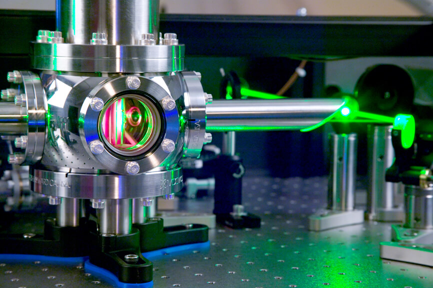
For single / multipass or regenerative amplifier systems with a low pulse repetition rate, a pulsed pump source is required, which is synchronized with the pulses to be amplified. For pulsed operation, a Q-switched neodymium-based infrared laser supplemented with a frequency doubler, as seen in Figure 3, is usually the only option.
Typical laser gain media for such pump lasers are Nd:YAG and Nd:YLF. These can store relatively large amounts of energy, which one can then easily extract within 100 ns or less. Nd:YLF, having a long upper-state lifetime of 480 µs, is particularly suitable for lower repetition rates (e.g. 1-3 kHz), whereas Nd:YAG is otherwise often preferred. In many cases, however, both media are similarly suitable. The pump power required for a final amplifier stage may be on the order of several hundred watts and should possess the following qualities:
- Green wavelength (A good match to the Ti:sapphire absorption band, also high-power lasers exist there.)
- Mode quality at focus (Mode quality affects amplification efficiency as well as amplified output mode. The desired characteristics are round, uniform and close to a flat-top beam or supergaussian.)
- Short pulse duration (Pulse duration is ideally </= 150 ns since this affects amplification efficiency.)
- Stability (long term, pulse to pulse and beam pointing)
[1] [email protected], (636) 916-4900, http://www.northropgrumman.com/ceolaser
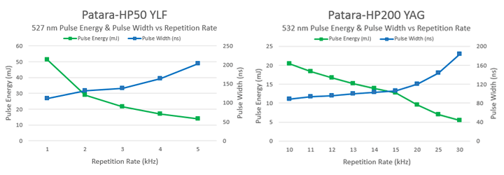
Pulse Energies at Varying Repetition Rates
The Patara-HP50 YLF can generate over 50 mJ of 527 nm pulse energy at 1 kHz and can be operated from single shot to 5 kHz. The Patara-HP200 YAG produces pulse energies of greater than 20 mJ at 532 nm at 10 kHz, and over 15 mJ from 11-13 kHz. The laser system can be operated at repetition rates from 10 – 30 kHz.. This means that amplifiers with signal output energies of many millijoules can be realized. Figure 4 represents pulse energy with respect to (WRT) repetition rate for each laser model.
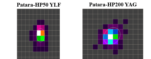
Beam Quality and Stability through the Rayleigh Range
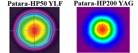
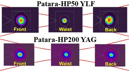
The beam quality is characterized with an M2 factor and both systems nominally output an M2 between 20 and 25. This is appropriate for pumping Ti:sapphire amplifiers in this pulse energy regime, where the pump beam does not have to be focused as tightly as for a mode-locked laser. Figure 5 represents typical beam images captured at the output window for each laser system. Figure 6 depicts a close to circular output beam profile with the beam radii in the horizontal and vertical direction differing by approximately less than 10% through the Rayleigh range.
Pulse Width, Pulse-to-Pulse Stability and Timing Jitter
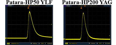
The pulse width for the Patara-HP50 YLF laser is specified at < 150 ns while the Patara-HP200 YAG laser is specified at < 120 ns. Each system is below 150 ns, i.e., far below the upper-state lifetime of Ti:sapphire, and the pulse energy for each system exhibits high stability; the pulse-to-pulse energy fluctuations are below 1.5% rms (Figure 7). Timing jitter, measured by the delay between the external trigger and laser pulse, is only a few nanoseconds for each laser system respectively.
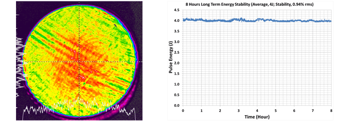
Long-Term Power Stability
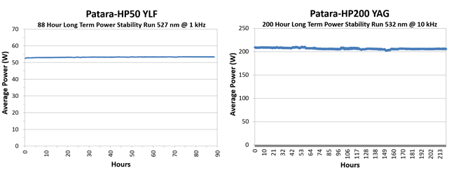
The long-term stability (over 8 hours) is less than 1% rms (Patara-HP50 YLF) and less than 2% rms (Patara-HP200 YAG). This is crucial since changes in pump pulse energy would translate into changes of signal pulse energy – particularly in a high-gain amplifier, where the gain depends on the pump pulse energy and gain saturation may not be strong. Figure 8 displays an 88 hour stability plot for the Patara-HP50 YLF laser and a 200 hour stability plot for the Patara-HP200 YAG laser system.
Beam Pointing Stability
Laser pointing stability is defined as an angular value in microradians (μrad). It is a measure of how much the beam position drifts from a target over time. Stability can be affected by a number of factors both internal and external to the laser itself, including physical motion, heat buildup, cavity instability, air currents and more. CEO has measured beam pointing stability for both Patara-HP systems to be approximately 25 μrad over a 30 minute period of time (specified < 50 μrad). Figure 9 depicts beam stability tracking (measured by beam profiling software) for each system.
Patara Laser System Reliability
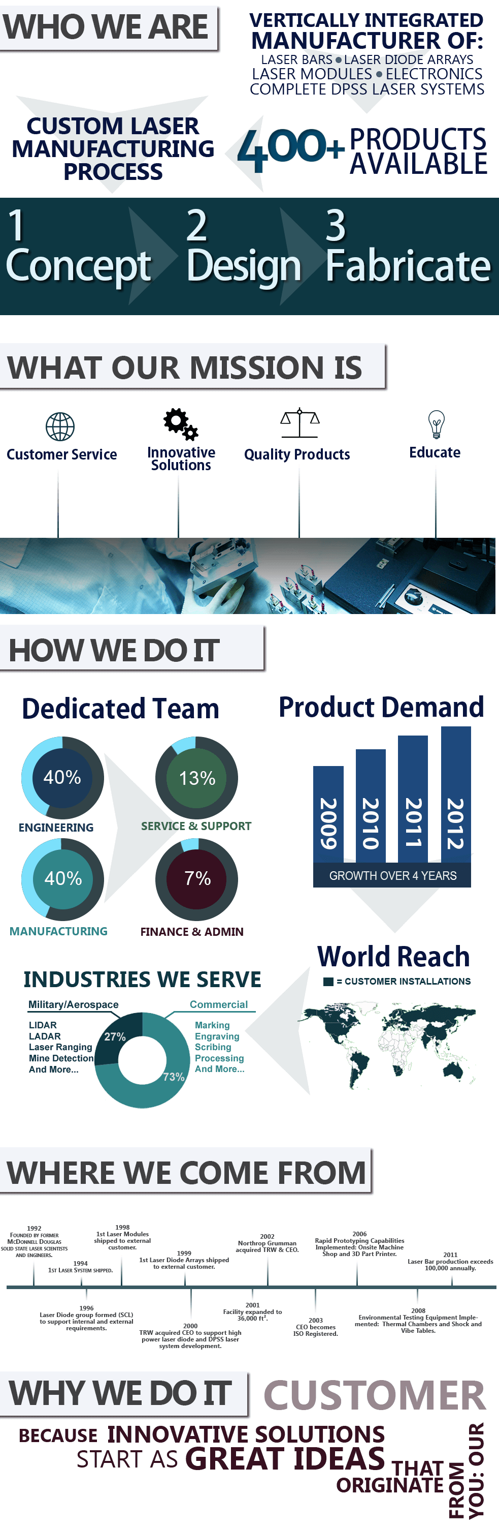
Cutting Edge Optronics is a vertically-integrated laser manufacturer, and controls all aspects of DPSS laser production at its facility in St. Charles, MO, USA. All laser diode arrays that are used in Patara lasers are fabricated in the same facility where the lasers are built. This allows the laser system designers and laser production managers to select diode arrays that are ideally suited for the laser being built.
In addition, CEO pulls sample material from every diode bar lot that flows through the factory. This material undergoes extensive characterization and a subsequent life test. This ensures that every diode array that is used in a Patara laser is of high quality. Records of these tests are maintained for all diode bar lots.
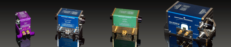
The laser diode arrays are packaged into CEO DPSS gain modules (see Figure 10) and fully characterized before being inserted into a Patara laser. Over 10,000 CEO gain modules have been installed worldwide for commercial, industrial, military and aerospace applications. Laser diode lifetime, in the lasers, routinely exceeds 15,000 hours.
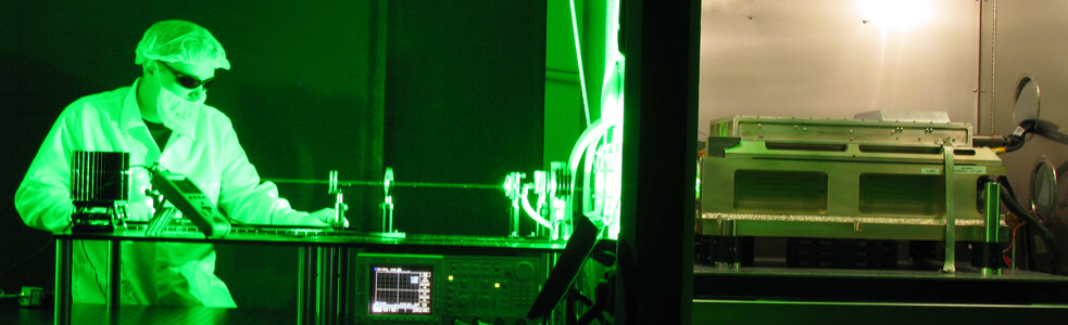
Each component in CEO’s pump lasers is thoroughly cleaned in CEO’s 400 ft² cleaning facility prior to assembly. All lasers are manufactured in a clean, particle controlled environment, and every laser is tested under full shock, vibration and environmental conditions (Figure 11) before it is certified for delivery.
All Patara-HP laser systems are delivered with CEO’s eDrive laser controller electronics, which are also manufactured at the CEO facility. The laser controller features extensive system protection interlocks and on-board diagnostics. All high current circuitry is isolated from low voltage control logic.
Gigashot™ Laser System
CEO also offers a short pulse, high energy Q-switched green laser system for pumping Ti:sapphire at repetition rates from 10-100 Hz. The Gigashot flat-top (FT) produces 160 mJ, 10 ns pulses at 100 Hz, 532 nm. This laser system is designed as a MOPA configuration (Master Oscillator, Power Amplifier) which can be seeded as well as amplified to >5 J (green) at 10 Hz with the addition of CEO’s REA amplifier modules (See Figure 12 for more information). The Gigashot-FT family is available in both YAG (532 nm) and YLF (527 nm) configurations. Additional repetition rates and pulse energies are available within a broad range of 10s of Hz to 100s of Hz. UV output (355 nm or 351 nm) is an additional option. The Gigashot-FT won the 2015 Lasers Focus World innovation award in the lasers and sources category. More information on the award can be found here: https://cuttingedgeoptronics.com/2015/05/01/lasers-and-sources-innovation-award-video/
Conclusion
With variable repetition rates from single shot to 30 kHz, and pulse energies up to 50 mJ, CEO’s Patara-HP Q-switched green lasers are ideally suited for pumping Ti:sapphire ultrafast amplifiers. Excellent beam quality combined with stable output (pulse to pulse, pointing, and long term) enable rock solid amplifier performance. Lasers from CEO’s Patara product line are operating in several hundred customer sites worldwide, with CEO’s long-lived, high power laser diodes forming the foundation of every laser system shipped from its St. Charles, MO, USA facility. The Patara-HP’s modular design allows it to be custom configured to operate within various application platforms. The Patara-HP laser systems have been successfully installed as pumps for a variety of regenerative and multi-pass ultrafast amplifier systems around the world. Backed by an experienced team of scientists and engineers, CEO’s Technical Services group ensures that the Patara-HP laser system performs to all customer expectations upon installation and throughout its long lifetime. CEO is dedicated to providing the highest quality products and services with the highest value to the customer.
Reference Links
Patara-HP50 YLF Laser
Patara-HP200 YAG Laser
120 mJ / 100 Hz / 355 nm Gigashot-FT Laser
5 Joule / 20 Hz / 527 nm Gigashot-FT Laser
2 Joule Laser Installation at LLNL
2 Joule DPSS Laser Video
10 Joule DPSS Laser Video
4 Joule Nd:YLF Laser for Pumping Ti:sapphire lasers
High Energy DPSS Laser Design Video
Approved for Public Release 17-1971
© 2017 Northrop Grumman Systems Corporation – All Rights Reserved