A low-SWaP (Size, Weight and Power) diode array has been developed for a high-power fiber-coupled application. High efficiency (~65%) diodes enable high optical powers while minimizing thermal losses. A large amount of waste heat is still generated and must be extracted. Custom ceramic microchannel-coolers (MCCs) are used to dissipate the waste heat. The custom ceramic MCC was designed to accommodate long cavity length diodes and micro-lenses. The coolers provide similar thermal performance as copper MCCs however they are not susceptible to erosion and can be cooled with standard filtered water.
The custom ceramic micro-channel cooled array was designed to be a form/fit replacement for an existing copper-based solution. Each array consisted of three-vertically stacked MCCs with 4 mm CL, 976 nm diodes and beam-shaping micro-optics. The erosion and corrosion resistance of ceramic array is intended to mitigate the risk of copper-based MCC corrosion failures. Elimination of the water delivery requirements (pH, resistivity and dissolved oxygen control) further reduces the system SWaP while maintaining reliability.
The arrays were fabricated and fully characterized. This work discusses the advantages of the ceramic MCC technology and describes the design parameters that were tailored for the fiber-coupled application. Additional configuration options (form/fit, micro-lensing, alternate coolants, etc.) and on-going design improvements are also discussed.
Jeremy Junghans, Ryan Feeler and Ed Stephens
Northrop Grumman Cutting Edge Optronics, 20 Point West Blvd., St. Charles, MO USA 63301
1. INTRODUCTION
Lightweight, high-power fiber-coupled pump diodes are a key component of fiber lasers for military and industrial applications. The Size, Weight and Power (SWaP) requirements of the pump diodes has significant impact on the overall system mass and efficiency. The pump diodes are often assembled using laser diode bars with optical powers greater than 150 W per bar and electrical-to-optical efficiencies of greater than 65%. It is essential that the laser diode bars be paired with a package that provides adequate thermal management, reliable electrical and mechanical interconnections and must incorporate the micro-lenses needed for high coupling efficiencies. Copper microchannel coolers (MCCs) have often been the package of choice for these systems. Copper MCCs are highly effective at extracting waste heat and they can also easily accommodate the micro-optics needed for fiber-coupling. Microchannel coolers can be tightly stacked to obtain a high optical power density while minimizing the overall package size.
Copper microchannel coolers provide excellent thermal performance, however the current technology also has several fundamental problems that adversely affect system reliability and SWaP requirements. The primary limitation of microchannel coolers is a result of being constructed from an electrically conductive material such as copper, which causes the electrical and cooling paths to coincide. In order to eliminate the risks associated with the electrification of the entire system, the laser diode bar must be electrically isolated from the coolant flow. This can be accomplished by mounting the bar to an isolating heat spreader before attaching it to the MCC, but this significantly increases the thermal resistance of the package and marginalizes the thermal performance of the microchannel cooler. Alternatively, a non-conducting cooling fluid – such as deionized (DI) water – can be used to provide the electrical isolation between the packaged laser diode bar and the rest of the system.
The vast majority of the current military, aerospace, and industrial implementations of copper microchannel coolers utilize deionized water as the cooling fluid. The use of deionized water in microchannel-cooled laser diode arrays has led to a number of well-documented failure mechanisms, most notably the erosion and corrosion of the microchannel coolers [1]. Minimization of the corrosion failure mechanism requires a great deal of attention be paid to the entire cooling system [2]. In particular, it requires that the chiller be equipped with a means of controlling the pH and resistivity of the water. The use of certain common plumbing materials (i.e. brass) is also forbidden. These requirements increase the cost, size, and complexity of the entire system, typically increasing the size of the chilled water system by a factor of two.
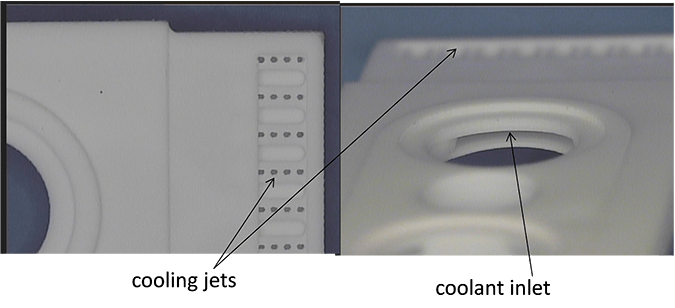
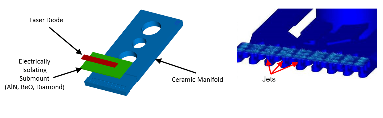
Northrop Grumman Cutting Edge Optronics (NG-CEO) previously developed ceramic microchannel coolers as an alternative to copper MCCs [3]. This patented[1] technology maintains many of the advantages of copper coolers while eliminating that erosion and corrosion concerns. The ceramic MCCs are designed to flow liquid from the inlet through cooling channels in the ceramic body (manifold) and through an array of cooling jets that directly impinge a high thermal conductivity, electrically isolating submount (Figure 1). These electrically isolating submounts (AlN, BeO, or diamond) perform as heat spreaders and eliminate the need for deionized water and decrease the thermal resistance of the package. Since the coolant is in direct contact with the submount, the low thermal conductivity of the ceramic cooler body material does not adversely affect the thermal performance of the device. CFD analysis is completed on each design to insure that the desired thermal performance is achieved (Figure 2). The size, location and number of impingement jets can be customized for specific bar sizes and flow requirements.
[1] This product falls under US Patent 7,656,915 B2.
2. EROSION TESTING
NG-CEO has conducted several erosion studies designed to understand the parameter space in which copper coolers can be operated reliably. The results of one such study are presented here to serve as a comparison to results obtained with the ceramic MCCs. A vertical stack of six copper MCCs was subjected to a flow rate of 0.2 GPM/cooler, which is approximately four times greater than the flow rate recommended by the manufacturer of the copper coolers. This was purely a test of the erosion properties of the coolers; no voltage or current was applied to the diode bars in the stack in order to eliminate the effects of galvanic corrosion.
At the conclusion of the erosion test, the top (mounting surface) layer of one of the coolers was removed and compared to an unused cooler. A picture of each cooler is shown in Figure 3. The water flow is such that it comes up through small holes near the front of the cooler (out of the page in Figure 3) and then away from the front of the cooler as indicated by the blue arrows. The zigzag pattern in the cooler is designed to promote turbulent flow and therefore improve the cooling properties of the MCC.
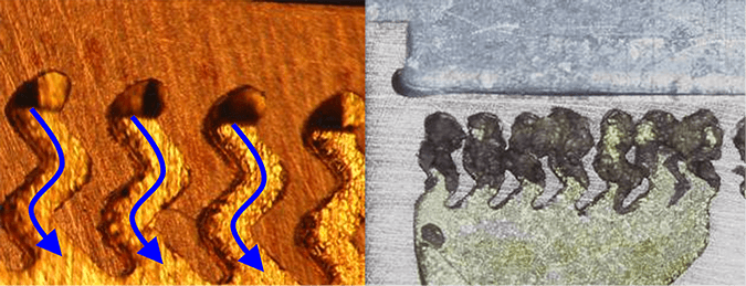
The effect of the high flow rate is clearly seen in the right hand side of Figure 3. Most of the structure that existed in the front of the cooler has been completely eroded by the water. The small holes in the front of the cooler that transport the water to the cooling layer have greatly expanded in size, and a significant portion of the zigzag pattern has been eroded away. This picture is representative of what has been observed in other tests conducted at high flow rates. Similar signs of erosion have been observed on all copper MCCs including straight-finned (rather than zigzag) designs. The effect is most pronounced in the areas with the highest fluid velocities which makes the zigzag portion of the cooler highly susceptible. However other portions of the cooler, such as the front of the cooler where the water transitions from the inlet to outlet channels, also see very high fluid velocities and rapid erosion during high flow rate operation.
A similar test has been conducted with three ceramic coolers, one cooler with each of the thermal window materials (AlN, BeO, and CVD diamond). These coolers were packaged into single-bar MCC arrays and placed in a life test system. A flow rate of 0.25 GPM/cooler was set for the devices and the system was allowed to run without any pH or resistivity control. After approximately 550 hours, the sample with a BeO thermal window was removed from the system. The thermal window was removed and the internal channels of the cooler were examined under a microscope. The bottom of the thermal window was also examined to look for signs of erosion from the impinging water. The other two samples were tested for an a total run time of approximately 2500 hours, at which time the sample with the AlN thermal window was removed for a similar analysis. Photographs of the internal structure of these two samples, along with an unused cooler, are shown in Figure 4.
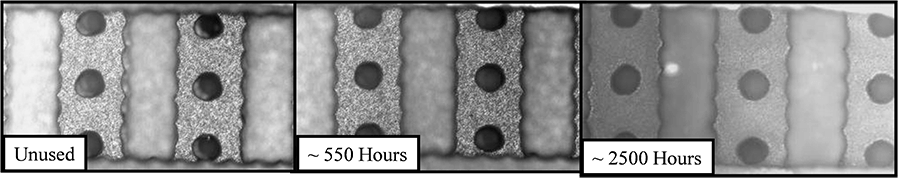
The performance differences between the copper and ceramic coolers in high flow conditions are striking. The ceramic coolers exhibit little (if any) erosion after 2500 hours at 0.25 GPM/cooler, whereas the copper coolers had eroded to the point of failure after 1000 hours at 0.2 GPM/cooler. Of equal importance is the erosion resistance of the thermal window materials. The BeO examined at 550 hours and the AlN examined at 2500 hours each showed very limited signs of erosion. This accelerated test was conducted at flow rates much higher than typical operating conditions for ceramic MCCs and demonstrates the robust nature of the ceramic coolers.
The resistance to erosion of the ceramic MCCs opens the door to a wide range of operating conditions. In applications where high flow rates are available, they can be used to improve the thermal performance of the devices with little negative impact on overall array lifetime. Elimination of the water delivery system requirements also reduces the size, cost and complexity of the chiller. These attributes make ceramic MCCs well-suited for high-power fiber-coupled pump diodes.
3. DEVELOPMENT OF ARRAY FOR HIGH-POWER FIBER-COUPLED APPLICATION
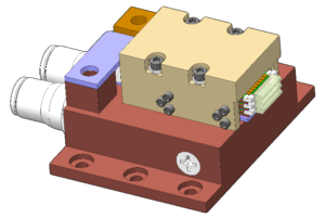
One of the great strengths of the ceramic coolers is the ease of design and manufacturing. This, coupled with NG-CEO’s CFD analysis, allows for the creation of custom coolers to meet a wide variety of applications. Coolers can be created with a wide range of pressure/flow characteristics, pitches, sizes, and shapes. In most cases an array can be designed that is a direct form and fit replacement of an existing array. This work details the development of a custom ceramic microchannel cooled pump diode. The array was designed to be a form/fit replacement for an existing copper-based solution. Each array consisted of three vertically-stacked ceramic MCCs with 4 mm CL, 976 nm diodes and beam-shaping micro-optics. The ceramic MCCs were designed to accommodate long cavity length diodes and micro-lenses that the fiber pump required. A picture of the modeled array is shown below (Figure 5).
Each array consisted of three ceramic microchannel coolers stacked to provide a 2 mm bar-to-bar pitch. A 19-emitter, 4 mm cavity length (CL) 976 nm diode bar was chosen. The 4 mm CL of the diode bar was however much longer (1-2 mm CL) than what was used on previous ceramic MCC designs. New MCCs were designed to efficiently cool the larger bar geometry.
The array was designed to be a drop-in replacement for an existing fiber pump. It was therefore critical that the beam heights of each bar matched that of the copper-based solution. The thickness tolerances of all components had to be minimized to maintain vertical pitch requirements. It was also essential that the electrical contacts provide reliable bar-to-bar connections while maintaining the mechanical pitch. Special attention was paid to the design and manufacturing tolerances of the deposited metals on laser diode submount and the n-side electrical contacts.
Each diode bar was paired with a beam twister micro-optic. The 19-emitter bar had an emitter-to-emitter pitch of 500 microns that allowed the use of commercial off the shelf beam twister (or beamPROP) micro-optics. The beam twister matches the beam parameter product of the diode’s fast and slow axes. The typically oval emission of each diode bar is subsequently transformed into a square-shaped output. This allows simple collimating lenses to be used to focus the light into the fiber and enables high coupling efficiencies to be achieved. Individual emitters are aligned to corresponding elements within the micro-optic. Fixtures were designed to allow each array to be actively aligned using one NG-CEO’s micro-lensing stations.
4. RESULTS
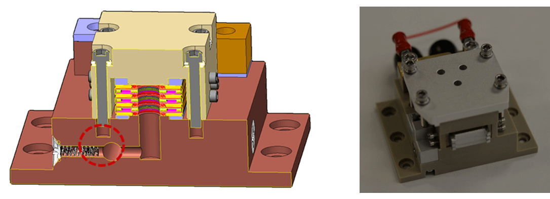
Several challenges were encountered during the assembly of the fiber-coupled arrays. Each individual MCC and array manifold component was subjected to a high-pressure nitrogen leak test. All individual mechanical components passed these leak checks. However, once the arrays were assembled it was discovered that the manifolds themselves were leaking. The location of the leak had been inadvertently sealed by the test fixture during the leak tests. It was determined that a portion of the tapped holes that were used to fasten the cap to the manifold were drilled too deep and subsequently intersected the cooling channels (Figure 6, left). These holes were sealed and a new lid was designed that did not require the use of these holes. The new design was implemented and all of the arrays passed the nitrogen and water leak tests (Figure 6, right). Additional design modifications have been since been identified that eliminate the need for the larger lid and further reduces SWaP requirements.
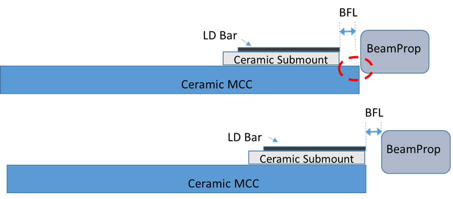
An additional challenge was encountered during the micro-lensing of the fiber-coupled array. Each beam twister is actively aligned to achieve the best results. The beam twisters that were chosen had a very short (0.07 mm) back focal length (BFL) compared to the typical fast axis collimating lenses that are used on many other applications which have a BFL 1.5x – 2x longer. As a result NG-CEO was unable to micro-lens a portion of the MCCs. Diode bars are precisely aligned to the front edge of each MCC’s integrated submount to achieve the optimal thermal and optical performance. However there is also a manufacturing tolerance associated with the placement of the submount onto the body of the ceramic MCC. It was found that a portion of the MCCs included submounts that were recessed slightly more than the BFL of the beam twister (i.e. >0.07 mm). A simple schematic illustrating this challenge is shown below (Figure 7). The top illustration shows that when the submount is recessed beyond the focal length of the optic, the lens crashes into the body of the MCC prior to achieving best focus. The MCCs were therefore screened based on submount location and the MCCs without recessed submounts (as depicted in the bottom illustration of Figure 7 were successfully lensed.
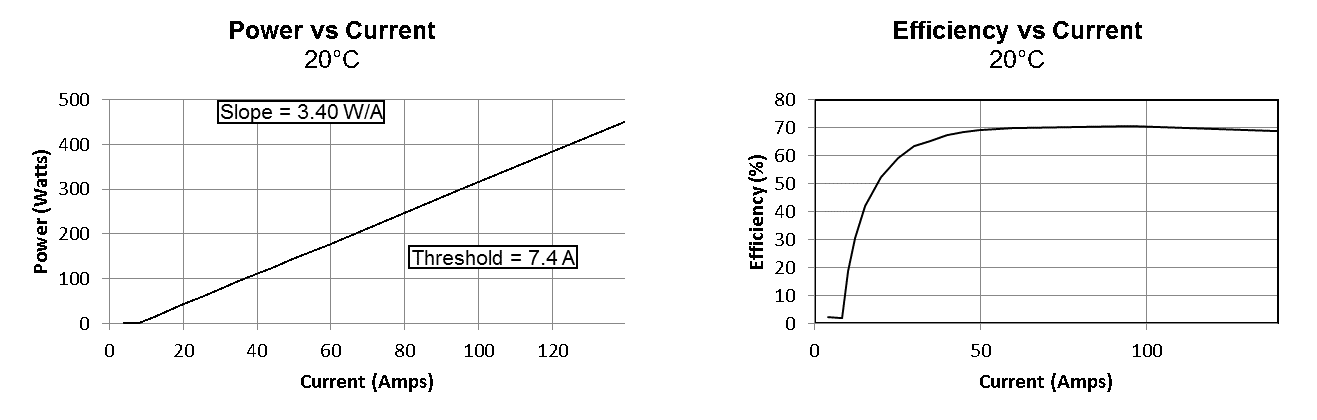
Each of the completed arrays was fully characterized at NG-CEO and also tested up to 150 A at the customer’s site. A plot of the P-I characteristics as well as the electrical-optical efficiency of one example array is shown in Figure 8. It can be seen that the slope remained linear across entire test range and approximately 70% E-O efficiency was obtained. A line width of less than 5.5 mRad (FWHM) was measured for the 3-bar array following micro-lensing.
5. SUMMARY AND CONCLUSIONS
Northrop Grumman Cutting Edge Optronics developed a custom ceramic microchannel cooled array for a high-power fiber-coupled application. The array was designed to be a form and fit replacement for an existing 3-bar Cu-based MCC array. The application required a custom ceramic MCC geometry and mechanical array design. The completed design provided greater than 150 W per bar at greater than 65% E-O efficiency. The use of ceramic MCCs eliminated the need for a pH and resistivity controlled chiller which further reduced SWaP requirements. The erosion and corrosion resistance of the ceramic array mitigates the risk of Cu-based MCC corrosion failures. Beam transformation micro-optics (Beam Twister or beamPROP) were used to enable efficient coupling to the fiber. Minor mechanical design and fabrication issues were encountered during assembly. Design and process modifications were put into place and the arrays were assembled. The completed arrays were tested at NG-CEO and its customer’s site and determined to meet the design requirements. Additional design and process modifications have been identified and will be implemented on the next builds.
REFERENCES
[1] Georg Truesch et. al., “Reliability of Water Cooled High Power Diode Laser Modules,” proc. of SPIE 5711, 132-141 (2005).
[2] John Haake and Brian Faircloth, “Requirements for Long Life Micro-Channel Coolers for Direct Diode Laser Systems,” proc. of SPIE 5711, 121-131 (2005).
[3] Ryan Feeler et. al., “Next-Generation Microchannel Coolers,” proc. of SPIE 6876, (2008).
Approved for Public Release 18-0426
© 2018 Northrop Grumman Systems Corporation – All Rights Reserved